Page 3 of 235
L/C 100_U3
2000 L/C 100 (OM60866U) 1. Headlight, turn signal and front fog
light switches
2. Cruise control switch
3. Ignition switch
4. Wiper and washer switches
5. Emergency flasher switch
6. Power antenna switch
7. Car audio
8. Clock and outside temperature display
9. Air conditioning controls
10. Outside rear view mirror heater switch 11. Rear air conditioning switch
12. Rear heater switch
13. Rear window defogger switch
14. Center differential lock switch
15. Manual tilt steering lock release lever
16. Power tilt and telescopic steering switch
17. Instrument panel light control dial
18. Power rear view mirror control switch
19. Power quarter window switch (left −hand
side)
20. Power quarter window switch (right −
hand side)
�
View B
Page 107 of 235

L/C 100_U129
2000 L/C 100 (OM60866U)
There must be at least 3 seconds of blank
space between tracks for the track button
to work correctly. In addition, the feature
may not work well with some spoken
word, live, or classical recordings.
ST (Stereo reception) display
Your radio automatically changes to stereo
reception when a stereo broadcast is re-
ceived. “ST” appears on the display. If the
signal becomes weak, the radio reduces
the amount of channel separation to prev-
ent the weak signal from creating noise.
If the signal becomes extremely weak, the
radio switches from stereo to mono recep-
tion.
TA P E
Push “TAPE” to switch from radio or com-
pact disc operation to cassette operation.
If the audio system is off, you can turn
on the cassette player by pushing “TAPE”.
In both cases, a cassette must already be
loaded in the player.
TRACK (Track up/down button):
Compact disc player
By using this button, you can skip up or
down to a different track.
Push either side of the track button until
the number of the track you want to listen
to appears on the display. If you want to
return to the beginning of the current
track, push the down side of the button
one time, quickly.
TUNE (Tuning)
Your Toyota has an electronic tuning radio
(ETR). Turn the knob clockwise to step up
the frequency. Turn the knob counterclock-
wise to step down the frequency.
NOTICE
To ensure the correct audio system
operation: �
Be careful not to spill beverages
over the audio system.
� Do not put anything other than a
cassette tape or Compact Disc into
the slot.
� The use of cellular phone inside or
near the vehicle may cause a noise
from the speakers of the audio sys-
tem which you are listening to.
However, this does not indicate a
malfunction.
RADIO RECEPTION
Usually, a problem with radio reception
does not mean there is a problem with
your radio—it is just the normal result of
conditions outside the vehicle.
For example, nearby buildings and terrain
can interfere with FM reception. Power
lines or telephone wires can interfere with
AM signals. And of course, radio signals
have a limited range. The farther you are
from a station, the weaker its signal will
be. In addition, reception conditions
change constantly as your vehicle moves.Car audio system operating
hints
Page 123 of 235

L/C 100_U145
2000 L/C 100 (OM60866U) OPERATION OF INSTRUMENTS AND
CONTROLS
Other equipment
Clock146
. . . . . . . . . . . . . . . . . . . . . . . . . . . . . . . . . . . . . . . . . . . . . . . . . . . . . .
Outside temperature display146
. . . . . . . . . . . . . . . . . . . . . . . . . . . . . . . . .
Cigarette lighter and ashtray147
. . . . . . . . . . . . . . . . . . . . . . . . . . . . . . . . .
Power outlets147
. . . . . . . . . . . . . . . . . . . . . . . . . . . . . . . . . . . . . . . . . . . . . .
Fuel pump shut −off system148
. . . . . . . . . . . . . . . . . . . . . . . . . . . . . . . . . .
Rear console box149
. . . . . . . . . . . . . . . . . . . . . . . . . . . . . . . . . . . . . . . . . . .
Glove box150
. . . . . . . . . . . . . . . . . . . . . . . . . . . . . . . . . . . . . . . . . . . . . . . . . .
Garage door opener box150
. . . . . . . . . . . . . . . . . . . . . . . . . . . . . . . . . . . .
Auxiliary boxes153
. . . . . . . . . . . . . . . . . . . . . . . . . . . . . . . . . . . . . . . . . . . . .
Cup holders156
. . . . . . . . . . . . . . . . . . . . . . . . . . . . . . . . . . . . . . . . . . . . . . . .
Tie −down hooks157
. . . . . . . . . . . . . . . . . . . . . . . . . . . . . . . . . . . . . . . . . . . .
Luggage cover158
. . . . . . . . . . . . . . . . . . . . . . . . . . . . . . . . . . . . . . . . . . . . .
Floor mat159
. . . . . . . . . . . . . . . . . . . . . . . . . . . . . . . . . . . . . . . . . . . . . . . . . .
SECTION 1− 9
Page 124 of 235
L/C 100_U
146 2000 L/C 100 (OM60866U)
Clock
The digital clock indicates the time.
The key must be in the ”ACC” or ”ON”
position.
To reset the hour: Push the ”H” button.
To reset the minutes: Push the ”M” button.
If quick adjustment to a full hour is de-
sired, push the ”:00” button.
For example, if the ”:00” button is de-
pressed when the time is between
1:01—1:29, the time will change to 1:00.
If the time is between 1:30—1:59, the
time will change to 2:00.
If the electrical power source has been
disconnected from the clock, the time dis-
play will automatically be set to 1:00 (one
o’clock).
When the instrument panel lights are
turned on, the brightness of the time in-
dication will be reduced.
Outside temperature displayThe outside temperature display indi-
cates the outside air temperature.
The key must be in the ”ON” position.
The display indicates between the range of
−22 °F and 122 °F.
Page 128 of 235
L/C 100_U
150 2000 L/C 100 (OM60866U)
Glove box
To use the glove box, do this.
To open: Pull the lever.
With the instrument panel lights on, the
glove box light will come on when the
glove box is open.
To lock: Insert the master key and turn it
clockwise.
CAUTION
To reduce the chance of injury in
case of an accident or a sudden stop,
always keep the glove box door
closed while driving.
Garage door opener box
Your vehicle is equipped with a box
designed to store a garage door opener
transmitter. You can operate the stored
garage door opener through the hole on
the lid.To use the garage door opener box, do
the following.
1. Open the garage door opener box with a flat −bladed screwdriver. To
protect the surface, put a sheet of
paper or cloth on the blade.
Page 166 of 235
L/C 100_U
202 2000 L/C 100 (OM60866U)
3. Insert the jack handle end into the low-
ering screw through the access hole
and turn it counterclockwise with push-
ing it to the front lightly.4. After the tire is lowered completely tothe ground, remove the holding bracket
as shown in the illustration.When storing the spare tire, put it in place
with the outer side of the wheel facing up
and hook the holding bracket as shown in
the illustration. Then secure the tire, tak-
ing care that the tire goes straight up
without catching on any other part, to pre-
vent it from moving during a collision or
sudden braking.
Check the tire from the side to see that
the tire is stored horizontally.
Page 167 of 235

L/C 100_U203
2000 L/C 100 (OM60866U)
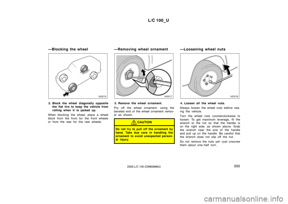
—Blocking the wheel
2. Block the wheel diagonally opposite
the flat tire to keep the vehicle from
rolling when it is j acked up.
When blocking the wheel, place a wheel
block from the front for the front wheels
or from the rear for the rear wheels. —Removing wheel ornament3. Remove the wheel ornament.
Pry off the wheel ornament, using the
beveled end of the wheel ornament remov-
er as shown.
CAUTION
Do not try to pull off the ornament by
hand. Take due care in handling the
ornament to avoid unexpected person-
al injury.
—Loosening wheel nuts
4. Loosen all the wheel nuts.
Always loosen the wheel nuts before rais-
ing the vehicle.
Turn the wheel nuts counterclockwise to
loosen. To get maximum leverage, fit the
wrench to the nut so that the handle is
on the right side, as shown above. Grab
the wrench near the end of the handle
and pull up on the handle. Be careful that
the wrench does not slip off the nut.
Do not remove the nuts yet—just unscrew
them about one −half turn.
Page 169 of 235

L/C 100_U205
2000 L/C 100 (OM60866U)
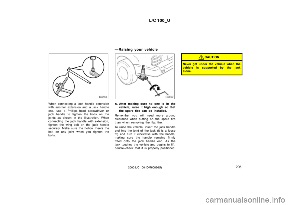
When connecting a jack handle extension
with another extension and a jack handle
end, use a Ph illips−head screwdriver or
jack handle to tighten the bolts on the
joints as shown in the illustration. When
connecting the jack handle with extension,
tighten the wing bolt on the jack handle
securely. Make sure the hollow meets the
bolt on any joint when you tighten the
bolts. —Raising your vehicle6. After making sure no one is in the
vehicle, raise it high enough so that
the spare tire can be installed.
Remember you will need more ground
clearance when putting on the spare tire
than when removing the flat tire.
To raise the vehicle, insert the jack handle
end into the joint of the jack (it is a loose
fit) and turn it clockwise with the handle,
making sure the handle remains firmly
fitted onto the jack handle end. As the
jack touches the vehicle and begins to lift,
double −check that it is properly positioned.
CAUTION
Never get under the vehicle when the
vehicle is supported by the jack
alone.