Page 2198 of 4770
V08249
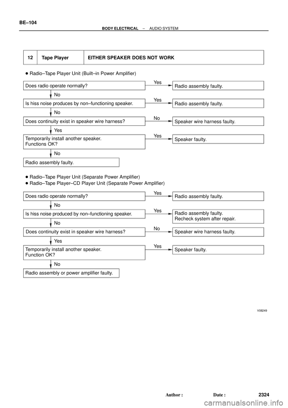
12
Tape Player EITHER SPEAKER DOES NOT WORK
� Radio±Tape Player Unit (Built±in Power Amplifier)
Does radio operate normally?
Is hiss noise produces by non±functioning speaker.
Does continuity exist in speaker wire harness?
Temporarily install another speaker.
Functions OK?
Radio assembly faulty.Radio assembly faulty.
Radio assembly faulty.
Speaker wire harness faulty.
Speaker faulty.
� Radio±Tape Player Unit (Separate Power Amplifier)
� Radio±Tape Player±CD Player Unit (Separate Power Amplifier)
Does radio operate normally?
Is hiss noise produced by non±functioning speaker.
Temporarily install another speaker.
Function OK?
Radio assembly or power amplifier faulty.Radio assembly faulty.
Radio assembly faulty.
Recheck system after repair.
Speaker wire harness faulty.
Speaker faulty. Ye s
No Ye s
Ye s Ye s
Ye sYe s
Ye s
Ye s No
No
No
No
No
NoNo
Does continuity exist in speaker wire harness? BE±104
± BODY ELECTRICALAUDIO SYSTEM
2324 Author�: Date�:
Page 2200 of 4770
 inserted?
Is there a foreign object inside tape player?
Operates no")
V08251
14 Tape Player TAPE JAMMED, MALFUNCTION WITH TAPE SPEED OR AUTO±REVERSE
Function OK if different tape (less than 120 mints.) inserted?
Is there a foreign object inside tape player?
Operates normally after cleaning the heads?
Radio assembly faulty.Cassette tape faulty.
Remove foreign object.
Head dirty. Ye s
No
Ye s
Ye s No
No
15 Tape Player CASSETTE TAPE WILL NOT BE EJECTED
� Radio±Tape Player Unit (Built±in Power Amplifier)
Does tape player operate normally?
Is auto search button of radio operating normally?
Check that RAD No.1 fuse is OK?
Is +B applied to radio assembly?
Radio assembly faulty.Cassette tape jammed.
Radio assembly faulty.
Replace fuse.
+B wire harness faulty.
� Radio±Tape Player Unit (Separate Power Amplifier)
� Radio±Tape Player±CD Player Unit (Separate Power Amplifier)
Does tape player operate normally?
Is auto search button of radio operating normally?
Check that RAD No.1 fuse is OK?
Is +B applied to power amplifier?
Is +B applied to radio assembly?
Radio assembly faulty.Cassette tape jammed.
Radio assembly faulty.
Replace fuse.
+B wire harness faulty.
Power amplifier faulty. No
Ye s
NG
OK
No No
NoNo
No
No Ye s
Ye s
Ye s
Ye s
Ye sYe s
NG
OK
BE±106
± BODY ELECTRICALAUDIO SYSTEM
2326 Author�: Date�:
Page 2201 of 4770

I03355I03355
16 CD Player CD CANNOT BE INSERTED
Is CD already inserted? Eject CD.
Is auto search button of radio operating normally? Is +B applied to CD player?Radio assembly
faulty.
Check that GND wire harness side
to CD player is OK?
CD player faulty.
Check that RAD No.1 fuse is OK?
Is +B applied to power amplifier?
Check that GND (wire harness side) to radio assembly is OK?
Radio assembly faulty.Replace fuse.
+B wire harness faulty. Ye s
No
Ye s
Ye s
Ye sNo
NoNG
OK
OK
OKNG
NG No
17 CD Player CD INSERTED, BUT NO POWER
Does radio operate normally?Is ACC applied to CD player?Radio assembly
faulty.
CD player faulty.
Check that RAD No.1 and No.2 fuse is OK?
Is ACC and +B, +B2 applied to power amplifier?
Is ACC and +B, +B2 applied to radio assembly?Replace fuse.
ACC and +B, +B2 wire harness faulty.
Power amplifier faulty.
Radio assembly faulty.Ye s
Ye s
Ye s
Ye sNoNo
No
No NG
OK
� Radio±CD Player Unit (Built±in Power Amplifier)
� Radio±CD Player Unit (Separate Power Amplifier)
� Radio±Tape Player ± CD Player (Separate Power Amplifier) � Radio±CD Player Unit (Built±in Power Amplifier)
� Radio±CD Player Unit (Separate Power Amplifier)
� Radio±Tape Player ± CD Player (Separate Power Amplifier)
± BODY ELECTRICALAUDIO SYSTEM
BE±107
2327 Author�: Date�:
Page 2202 of 4770
I03356
18 CD Player POWER COMING IN, BUT CD PLAYER NOT OPERATING
Is CD inserted with correct side up?
Function OK if different CD inserted?
Does radio operate normally?Insert correctly.
CD faulty.
Is temperature inside cabin hot?
Protective circuit in
operation.
Has sudden temperature change
occurred inside cabin?
CD player faulty.
Does continuity exist in speaker wire harness?
Temporarily install another speaker.
Functions OK?
Hissing sound from speaker?
Radio assembly faulty.
Recheck system after repair.Speaker wire harness faulty.
Speaker faulty.
Power amplifier faulty.
Recheck system after repair. No
Ye s Ye s
Ye s
Ye s
Ye s
Ye s
Ye sYe s No
No
No
No
No No No � Radio±CD Player Unit (Built±in Power Amplifier)
� Radio±CD Player Unit (Separate Power Amplifier)
� Radio±Tape Player ± CD Player (Separate Power Amplifier)
Formation of condensation
due to temp. changes. BE±108
± BODY ELECTRICALAUDIO SYSTEM
2328 Author�: Date�:
Page 2204 of 4770

I03358
Does radio operate normally?
Is hiss noise produced by non±functioning speaker?
Does continuity exist in speaker wire harness?
Temporarily install another speaker.
Function OK.
Power amplifier faulty.
Recheck system after repair.CD player.
Radio assembly faulty.
Recheck system after repair.
Speaker wire harness faulty.
Speaker faulty. Ye sYe s
Ye s
Ye s No
No
NoNo 21 CD Player EITHER SPEAKER DOES NOT WORK
22 CD Player CD WILL NOT BE EJECTED
Is auto search button of radio
operating normally?Is +B applied to CD player?Radio assembly
faulty.
CD player faulty. Ye s N o
Ye s
No
Check that RAD No.1 fuse is OK?Replace fuse.
Is +B and +B2 applied to power amplifier?
Is +B and +B2 applied to radio assembly?
Radio assembly faulty.+B wire harness faulty.
Power amplifier faulty. OK
Ye s
Ye sNG
No
No � Radio±CD Player Unit (Built±in Power Amplifier)
� Radio±CD Player Unit (Separate Power Amplifier)
� Radio±Tape Player ± CD Player (Separate Power Amplifier)
� Radio±CD Player Unit (Built±in Power Amplifier)
� Radio±CD Player Unit (Separate Power Amplifier)
� Radio±Tape Player ± CD Player (Separate Power Amplifier) BE±110
± BODY ELECTRICALAUDIO SYSTEM
2330 Author�: Date�:
Page 3636 of 4770

8. REMOVE GLOVE COMPARTMENT ASSEMBLY
(a) Using a screwdriver, remove the glove compartmen")
N20988
N21023
7 Clips
N21024
6 Clips BO±76
± BODYINSTRUMENT PANEL
2434 Author�: Date�:
2001 CAMRY (RM819U)
8. REMOVE GLOVE COMPARTMENT ASSEMBLY
(a) Using a screwdriver, remove the glove compartment door
finish plate to the glove compartment box inside.
NOTICE:
When handling the airbag connector, be careful not to dam-
age the airbag wire harness.
HINT:
Tape the screwdriver tip before use.
(b) Pull up and disconnect the airbag connector.
(c) Remove the 4 screws, bolt and glove compartment as-
sembly.
9. REMOVE CENTER CONSOLE UPPER PANEL
Using a screwdriver, remove the panel, then disconnect the
connector.
HINT:
Tape the screwdriver tip before use.
10. REMOVE REAR CONSOLE BOX
Remove the 2 bolts, 2 screws and the console box.
11. REMOVE CENTER CLUSTER FINISH PANEL
Using a screwdriver, remove the panel, then disconnect the
connector.
HINT:
Tape the screwdriver tip before using.
12. REMOVE FRONT CONSOLE BOX
Remove the 2 screws and the front console box.
13. REMOVE RADIO ASSEMBLY
14. REMOVE A/C CONTROL ASSEMBLY
(See page AC±88 and AC±95)
15. REMOVE HAZARD WARNING SWITCH
16. REMOVE CLUSTER FINISH PANEL
(a) Remove the 2 screws.
(b) Using a screwdriver, remove the panel.
HINT:
Tape the screwdriver tip before use.
17. REMOVE COMBINATION METER
18. REMOVE REMOTE CONTROL MIRROR HOLE BASE
Page 3638 of 4770

(f) Remove the bolt, nut, screw and the instrument panel as-
sembly.
23. REMOVE INSTRUMENT PANEL B")
N20994
N20995
N20996
N20997
BO±78
± BODYINSTRUMENT PANEL
2436 Author�: Date�:
2001 CAMRY (RM819U)
(f) Remove the bolt, nut, screw and the instrument panel as-
sembly.
23. REMOVE INSTRUMENT PANEL BRACES
(a) Remove the wire brackets and connector.
(b) Remove the bolt and connector from the No.1 instrument
panel brace.
(c) w/ Wireless Control:
Remove the nut and the wireless control unit from the
No.1 instrument panel brace.
(d) Remove the nut holding the radio antenna to the No.2
instrument panel brace.
(e) Remove a nut and brace mount bracket.
(f) Remove the 6 nuts, 2 bolts and No.1 and No.2 instrument
panel braces.
24. REMOVE INSTRUMENT PANEL REINFORCEMENT
(a) Remove the connectors from the steering column tube.
(b) Remove the 4 wire brackets and connectors.
(c) Remove the 2 nuts and bolt holding the No.1 Junction Box
(J/B) to the reinforcement.
(d) Remove the 4 nuts and the steering column from the rein-
forcement.
(e) Remove the brake pedal spring from the reinforcement
and brake pedal.
(f) Remove the 4 nuts, 3 bolts and the reinforcement.
Page 3688 of 4770

± INTRODUCTIONFOR ALL OF VEHICLES
IN±17
17 Author�: Date�:
2. FOR VEHICLES EQUIPPED WITH A CATALYTIC CONVERTER
CAUTION:
If large amount of unburned gasoline flows into the converter, it may overheat and create a fire haz-
ard. To prevent this, observe the following precautions and explain them to your customer.
(a) Use only unleaded gasoline.
(b) Avoid prolonged idling.
Avoid running the engine at idle speed for more than 20 minutes.
(c) Avoid spark jump test.
(1) Perform spark jump test only when absolutely necessary. Perform this test as rapidly as possible.
(2) While testing, never race the engine.
(d) Avoid prolonged engine compression measurement.
Engine compression tests must be done as rapidly as possible.
(e) Do not run engine when fuel tank is nearly empty.
This may cause the engine to misfire and create an extra load on the converter.
(f) Avoid coasting with ignition turned off.
(g) Do not dispose of used catalyst along with parts contaminated with gasoline or oil.
3. IF VEHICLE IS EQUIPPED WITH MOBILE COMMUNICATION SYSTEM
For vehicles with mobile communication systems such as two±way radios and cellular telephones, observe
the following precautions.
(1) Install the antenna as far as possible away from the ECU and sensors of the vehicle's electronic
system.
(2) Install the antenna feeder at least 20 cm (7.87 in.) away from the ECU and sensors of the ve-
hicle's electronic systems. For details about ECU and sensors locations, refer to the section on
the applicable component.
(3) Avoid winding the antenna feeder together with other wiring as much as possible, and also avoid
running the antenna feeder parallel with other wire harnesses.
(4) Check that the antenna and feeder are correctly adjusted.
(5) Do not install powerful mobile communications system.