Page 217 of 4770
Fuel pumped up by the fuel pump, flows through the fuel filter and is distributed to each injector
at a set pressure maintained by the pressure regulator.
The fuel pressure regulator adjusts the pressure of the fuel from the fuel line (high pressure side)
to a pressure 284 kPa (2.9 kgf/cm�, 41 psi) higher than the pressure inside the cylinder head, and
excess fuel is returned to the fuel tank through the return pipe.
The pulsation damper absorbs the slight fluctuations in fuel pressure caused by fuel injector from
the injector.
The injectors operate on input of injection signals from the ECM and inject fuel into the cylinder
head.
OPERATION
FUEL SYSTEM
± 5S±FE ENGINEMFI/SFI SYSTEMEG1±167
Page 228 of 4770
2. CHECK FUEL PRESSURE
(a) Check that the battery voltages is above 12 volts.
(b) Disconnect the negative (±) terminal cable from the
battery.
CAUTION: Work must be started after 90 seconds from
the time the ignition switch is turned to the ªLOCKº
position and the negative (±) terminal cable is discon±
nected from the battery.
If there is no pressure, check the following parts:
wFusible link
wFuses (AM2 30A, EFI 15A, IGN 7.5A)
wEFI main relay
wFuel pump
wWiring connections (c) Check that there is pressure in the hose from the fuel
filter.
HINT: At this time, you will hear fuel return noise.
(e) Remove the SST.
SST 09843±18020 (d) Turn the ignition switch OFF.
± 5S±FE ENGINEMFI/SFI SYSTEMEG1±178
Page 229 of 4770
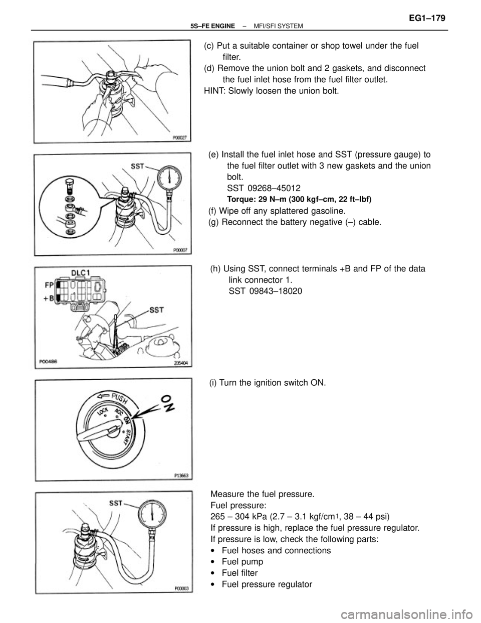
Measure the fuel pressure.
Fuel pressure:
265 ± 304 kPa (2.7 ± 3.1 kgf/cm�, 38 ± 44 psi)
If pressure is high, replace the fuel pressure regulator.
If pressure is low, check the following parts:
wFuel hoses and connections
wFuel pump
wFuel filter
wFuel pressure regulator (e) Install the fuel inlet hose and SST (pressure gauge) to
the fuel filter outlet with 3 new gaskets and the union
bolt.
SST 09268±45012
Torque: 29 N±m (300 kgf±cm, 22 ft±lbf)
(f) Wipe off any splattered gasoline.
(g) Reconnect the battery negative (±) cable. (c) Put a suitable container or shop towel under the fuel
filter.
(d) Remove the union bolt and 2 gaskets, and disconnect
the fuel inlet hose from the fuel filter outlet.
HINT: Slowly loosen the union bolt.
(h) Using SST, connect terminals +B and FP of the data
link connector 1.
SST 09843±18020
(i) Turn the ignition switch ON.
± 5S±FE ENGINEMFI/SFI SYSTEMEG1±179
Page 233 of 4770
5. DISCONNECT FUEL PIPE AND HOSE FROM FUEL
PUMP BRACKET
CAUTION: Remove the fuel filter cap to prevent the fuel
from flowing out.
(a) Using SST, disconnect the outlet pipe from the pump bracket.
SST 09631±22020
(b) Disconnect the return hose from the pump bracket. 3. REMOVE FLOOR SERVICE HOLE COVER
(a) Disconnect the fuel pump connector.
(b) Remove the 5 screws and service hole cover.
4. REMOVE FUEL PUMP LEAD WIRE
6. REMOVE FUEL PUMP BRACKET ASSEMBLY FROM
FUEL TANK
(a) Remove the 8 bolts.
(b) Pull out the pump bracket assembly.
(c) Remove the gasket from the pump bracket.
± 5S±FE ENGINEMFI/SFI SYSTEMEG1±183
Page 235 of 4770
FUEL PUMP ASSEMBLY
(See Components for Disassembly and Assembly)
1. INSTALL CONNECTOR
Install the gasket, connector and connector support
with the 2 screws.
2. INSTALL FUEL PUMP FILTER TO FUEL PUMP
Install the pump filter with a new clip.
4. INSTALL FUEL PUMP TO FUEL PUMP BRACKET
(a) Install the rubber cushion to the fuel pump.
(b) Connect the fuel hose to the outlet port of the fuel
pump.
(c) Install the fuel pump by pushing the lower side of the
fuel pump.
(d) Install the fuel pump connector. 3. INSTALL FUEL SENDER GAUGE TO FUEL PUMP
BRACKET
(a) Install the sender gauge with the 2 screws.
(b) Connect the fuel sender gauge connector. 4. REMOVE CONNECTOR
Remove the 2 screws, connector support, connector
and gasket. 3. REMOVE FUEL PUMP FILTER FROM FUEL PUMP
(a) Using a small screwdriver, remove the clip.
(b) Pull out the pump filter.
± 5S±FE ENGINEMFI/SFI SYSTEMEG1±185
Page 245 of 4770
(c) Install a new O±ring to the fuel inlet of pressure
regulator.
(d) Connect SST (hose) to the fuel inlet of the pressure
regulator with SST (union) and the 2 bolts.
SST 09268±41045 (09268±41090)
Torque: 5.4 N±m (55 kgf±cm, 48 ft±lbf)
(e) Connect the fuel return hose to the fuel outlet of the
pressure regulator with SST (union), 2 new gaskets
and union bolts. (a) Disconnect the fuel hose from the fuel filter outlet.
(b) Connect SST (union and hose) to the fuel filter outlet
with 2 new gaskets and union bolts.
SST 09268±41045 (90405±09015)
Torque: 29 N±m (300 kgf±cm, 22 ft±lbf)
HINT: Use the vehicle's fuel filter.
INJECTORS INSPECTION
1. INSPECT INJECTOR INJECTION
CAUTION: Keep injector clear of sparks during the test.
(f) California:
Remove the 2 O±rings, insulator and grommet from
each injector.
(g) Except California:
Remove the O±ring and grommet from each injector.
± 5S±FE ENGINEMFI/SFI SYSTEMEG1±195
Page 476 of 4770
Check operation of VSV when battery positive
voltage is applied and released to the VSV termi±
nals.
Battery positive voltage is applied:
The air from port E is flowing out through the
air filter.
Battery positive voltage is not applied:
The air from port E is flowing out through port
G. (1) Disconnect VSV connector.
(2) Remove VSV.
(1) Measure resistance between terminals.
(2) Measure resistance between each terminal
and the body.
(1) Resistance: 33 ± 39� at 20�C (68�F)
(2) Resistance: 1 M� or higher.
Check VSV for fuel pressure control.
Replace VSV for fuel pressure control VSV.
INSPECTION PROCEDURE
G o to step
± 5S±FE ENGINECIRCUIT INSPECTIONEG1±426
Page 599 of 4770

Replacement Parts
QUARTER PANEL
1. Cut and join the parts at the location shown above.HINT: Bend the roof drip channel at the upper part of the cut
and join location.
HOW TO USE T")
QUARTER PANEL (CUT)
Replacement Parts
QUARTER PANEL
1. Cut and join the parts at the location shown above.HINT: Bend the roof drip channel at the upper part of the cut
and join location.
HOW TO USE THIS MANUAL
Each repair method description provided in Section RE of this manual comprises two pages, divided into 2
blocks (REMOVAL AND INSTALLATION) and includes illustrations to facilitate body repair.
BODY PANEL REPLACEMENT
RE±38
REMOVAL
[Cut and Join Location]
Make Incision
Cut and Join Location
200 mm
Fuel Filler Opening Lid
2. Replace the fuel filter opening lid at the same time
as the quarter panel.
REPLACEMENT PARTS AND METHOD
(CUT)
Replacement method
(ASSY) Assembly replacement. . . . .
(CUT) Major cutting (less than 1/2 of parts used). . . . . .
(CUT±H) Half cutting (about 1/2 of parts used). . . .
(CUT±P) Partial cutting (most of parts used). . . .
PARTS LOCATION
REMOVAL DIAGRAM
Describes in detail removal of the damaged parts involving repair by cutting.
REMOVAL GUIDE
Provides additional information to more efficiently help you perform the removal.
INTRODUCTIONIN-2

 Check that the battery voltages is above 12 volts.
(b) Disconnect the negative (±) terminal cable from the
battery.
CAUTION: Work must be started after 90 seconds from
the")
 Using SST, disconnect the outlet pipe from the pump bracket.
SS")

1. INSTALL CONNECTOR
Install the gasket, connector and connector support
with the 2 screws.
2. INSTALL FUEL PUMP FILTER TO FUEL PUMP
In")
 Install a new O±ring to the fuel inlet of pressure
regulator.
(d) Connect SST (hose) to the fuel inlet of the pressure
regulator with SST (union) and the 2 bolts.
SST 09268±41045 (09268±41")
