Page 132 of 447
7B-90 AUTOMATIC TRANSMISSION (4 A/T)
ASSEMBLY
1) Install pump body oil seal (1)
Use special tool and hammer to install it, and then apply
grease to its lip portion.
Special tool
(A) : 09913-85210
“A”: Grease 99000-25030
2) Install driven gear and drive gear to pump body (2) after
applying A/T fluid to gears.
3) Install stator shaft assembly to pump body and tighten 11
pump cover bolts to specification.
Tightening torque
Oil pump cover bolts (a) : 10 N·m (1.0 kg-m, 7.5 lb-ft)
4) Install 2 new oil seal rings to stator shaft.
5) Apply grease to 2 oil seal rings.
6) Install new D-ring to which grease is applied and make sure
that it is not twisted or extruded.
7) Check drive gear for smooth rotation.
Page 134 of 447

7B-92 AUTOMATIC TRANSMISSION (4 A/T)
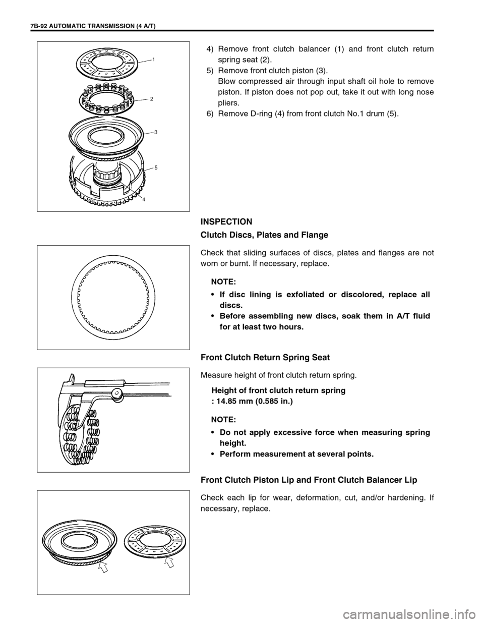
4) Remove front clutch balancer (1) and front clutch return
spring seat (2).
5) Remove front clutch piston (3).
Blow compressed air through input shaft oil hole to remove
piston. If piston does not pop out, take it out with long nose
pliers.
6) Remove D-ring (4) from front clutch No.1 drum (5).
INSPECTION
Clutch Discs, Plates and Flange
Check that sliding surfaces of discs, plates and flanges are not
worn or burnt. If necessary, replace.
Front Clutch Return Spring Seat
Measure height of front clutch return spring.
Height of front clutch return spring
: 14.85 mm (0.585 in.)
Front Clutch Piston Lip and Front Clutch Balancer Lip
Check each lip for wear, deformation, cut, and/or hardening. If
necessary, replace.
NOTE:
If disc lining is exfoliated or discolored, replace all
discs.
Before assembling new discs, soak them in A/T fluid
for at least two hours.
NOTE:
Do not apply excessive force when measuring spring
height.
Perform measurement at several points.
Page 138 of 447

7B-96 AUTOMATIC TRANSMISSION (4 A/T)
DISASSEMBLY
1) Remove snap ring.
2) Remove flange (1), discs and plates.
3) Remove shaft snap ring (1).
Compress piston return springs and remove shaft snap ring.
Place special tool (clutch spring compressor) on spring seat
and compress spring with a press (2), and then remove shaft
snap ring, using a flat end rod or the like (3).
Special tool
(A) : 09926-96020
4) Remove rear clutch balancer (1) and rear clutch return
spring seat (2).
5) Remove rear clutch piston (3).
If piston does not pop out, blow compressed air through
input shaft oil hole to remove piston.
6) Remove D-ring, and oil seals from input shaft subassembly
(4).
INSPECTION
Clutch Discs, Plates and Flange
Check that sliding surfaces of discs, plates and flanges are not
worn or burnt. If necessary, replace.
CAUTION:
Do not push down return spring more than necessary.
NOTE:
If disc lining is exfoliated or discolored, replace all
discs.
Before assembling new discs, soak them in A/T fluid
for at least two hours.
Page 143 of 447
AUTOMATIC TRANSMISSION (4 A/T) 7B-101
4) Remove direct clutch balancer (1) and direct clutch return
spring seat (2).
5) Remove direct clutch piston (3).
Blow compressed air through input shaft oil hole to remove
piston. If piston does not pop out, take it out with long nose
pliers.
6) Remove D-ring (4) from direct clutch No.1 drum (5).
INSPECTION
Clutch Discs, Plates and Flange
Check that sliding surfaces of discs, plates and flanges are not
worn or burnt. If necessary, replace.
Direct Clutch Return Spring Seat
Measure height of direct clutch return spring.
Height of direct clutch return spring
: 16.3 mm (0.642 in.)
.
NOTE:
If disc lining is exfoliated or discolored, replace all
discs.
Before assembling new discs, soak them in A/T fluid
for at least two hours.
NOTE:
Do not apply excessive force when measuring spring
height.
Perform measurement at several points.
Page 144 of 447

7B-102 AUTOMATIC TRANSMISSION (4 A/T)
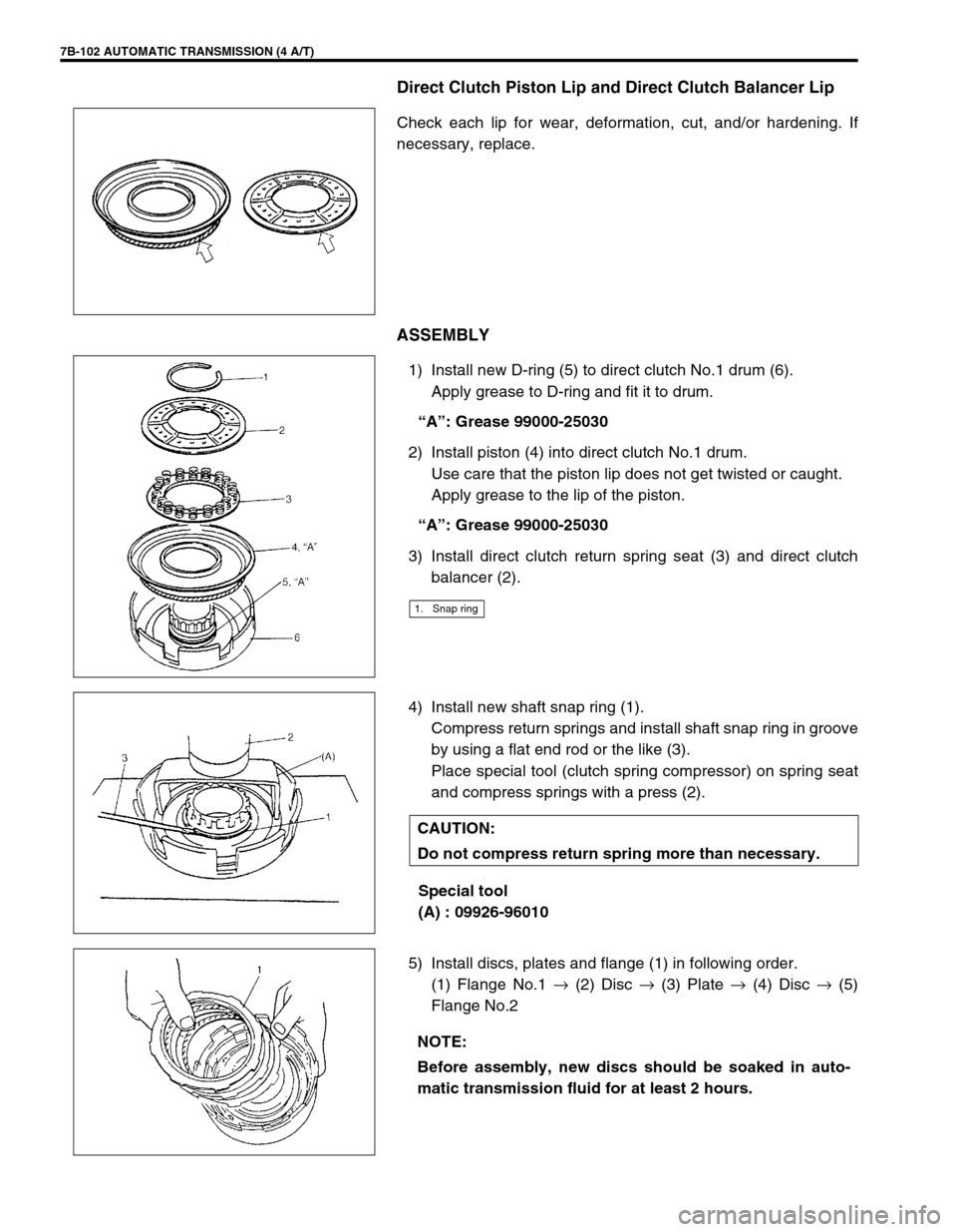
Direct Clutch Piston Lip and Direct Clutch Balancer Lip
Check each lip for wear, deformation, cut, and/or hardening. If
necessary, replace.
ASSEMBLY
1) Install new D-ring (5) to direct clutch No.1 drum (6).
Apply grease to D-ring and fit it to drum.
“A”: Grease 99000-25030
2) Install piston (4) into direct clutch No.1 drum.
Use care that the piston lip does not get twisted or caught.
Apply grease to the lip of the piston.
“A”: Grease 99000-25030
3) Install direct clutch return spring seat (3) and direct clutch
balancer (2).
4) Install new shaft snap ring (1).
Compress return springs and install shaft snap ring in groove
by using a flat end rod or the like (3).
Place special tool (clutch spring compressor) on spring seat
and compress springs with a press (2).
Special tool
(A) : 09926-96010
5) Install discs, plates and flange (1) in following order.
(1) Flange No.1 →
(2) Disc →
(3) Plate →
(4) Disc →
(5)
Flange No.2
1. Snap ring
CAUTION:
Do not compress return spring more than necessary.
NOTE:
Before assembly, new discs should be soaked in auto-
matic transmission fluid for at least 2 hours.
Page 160 of 447

7B-118 AUTOMATIC TRANSMISSION (4 A/T)
2) Install new oil seal to transmission case.
Use special tool to press-fit oil seal until oil seal end face is
flush with transmission case end face.
Special tool
(F) : 09913-75510
UNIT ASSEMBLY
CAUTION:
Automatic transmission consists of highly precise parts. As even a flaw in a small part may cause
oil leakage or decrease in function, check each part carefully before installation.
Clean all parts with compressed air. Never use wiping cloths or rags.
Before assembling new clutch discs and brake band, soak them in automatic transmission fluid for
at least 2 hours.
Be sure to use new gaskets and O-rings.
Lubricate O-rings with automatic transmission fluid.
Apply automatic transmission fluid on sliding or rotating surfaces of the parts before assembly.
Use yellow petrolatum grease or Suzuki Super Grease C to retain parts in place.
Be sure to install thrust bearings and races in correct direction and position.
Make sure that snap ring ends are not aligned with one of cutouts and are installed in groove cor-
rectly.
Do not use adhesive cements on gaskets and similar parts.
Be sure to torque each bolt and nut to specification.
Page:
< prev 1-8 9-16 17-24