Page 121 of 447
AUTOMATIC TRANSMISSION (4 A/T) 7B-79
4) Remove output shaft speed sensor (1) and input shaft speed
sensor (2).
5) Remove transmission range sensor (3).
6) Remove dropping resistor (4).
7) Remove breather hose (5).
8) Remove A/T fluid level gauge (1) and filler tube (2).
9) Remove vehicle speed sensor (1) (for speedometer), shift
cable bracket (2) and connector clamp bracket (3).
10) Remove oil pan and oil pan gasket.
11) Remove oil strainer assembly (1), and detach transmission
temperature sensor (2).
NOTE:
For removal of oil pan, do not turn transmission over
as this will contaminate valve body with foreign materi-
als in the bottom of oil pan.
When removing oil pan, tap around it lightly with a
plastic hammer. Do not force it off by using a screw-
driver or the like.
Page 201 of 447

TRANSFER 7D-3
ON-VEHICLE SERVICE
OIL CHANGE
1) Before changing or inspecting oil, be sure to stop engine and
lift vehicle horizontally.
2) With vehicle lifted up, check oil level and leakage. If leakage
exists, correct or repair it.
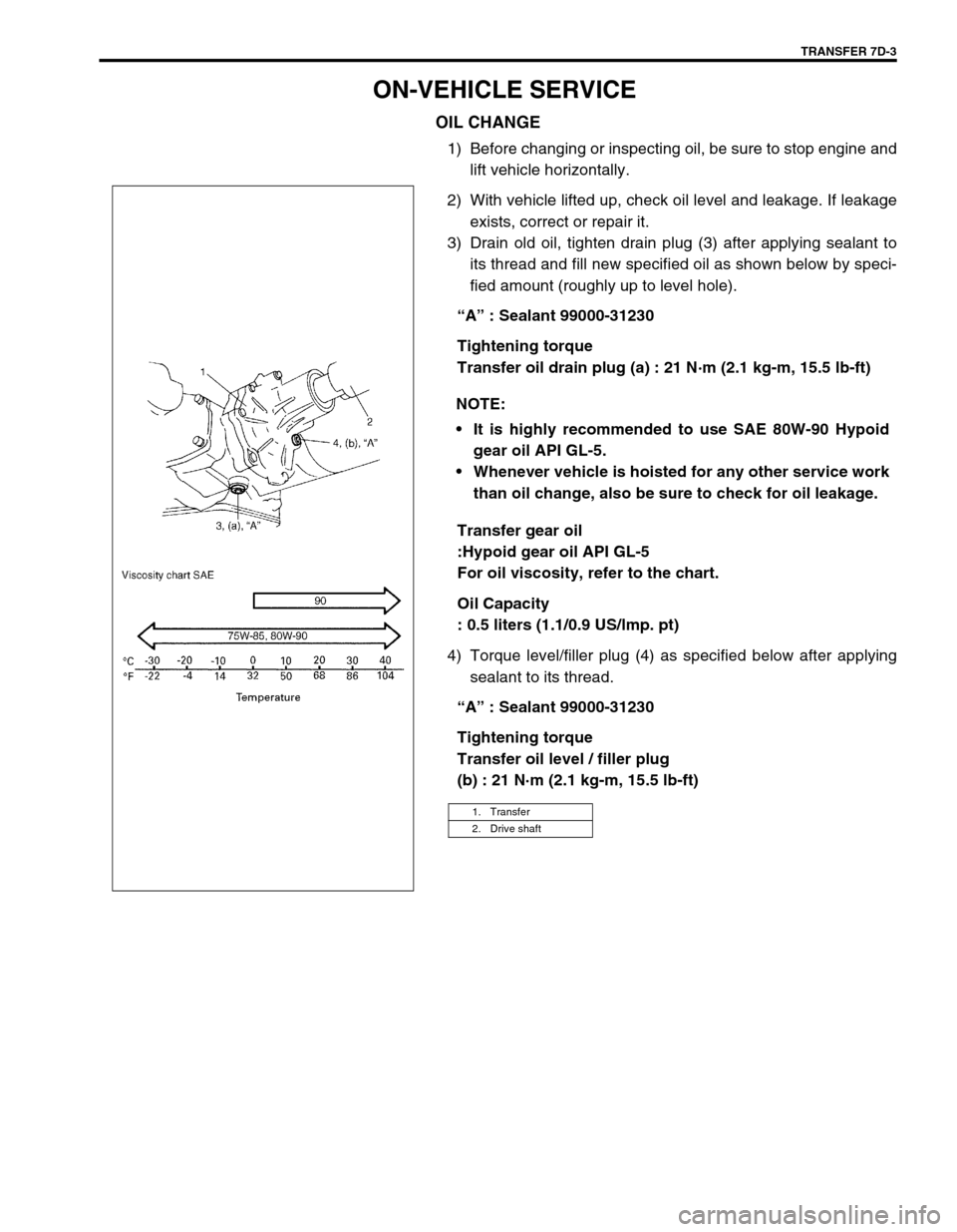
3) Drain old oil, tighten drain plug (3) after applying sealant to
its thread and fill new specified oil as shown below by speci-
fied amount (roughly up to level hole).
“A” : Sealant 99000-31230
Tightening torque
Transfer oil drain plug (a) : 21 N·m (2.1 kg-m, 15.5 lb-ft)
Transfer gear oil
:Hypoid gear oil API GL-5
For oil viscosity, refer to the chart.
Oil Capacity
: 0.5 liters (1.1/0.9 US/lmp. pt)
4) Torque level/filler plug (4) as specified below after applying
sealant to its thread.
“A” : Sealant 99000-31230
Tightening torque
Transfer oil level / filler plug
(b) : 21 N·m (2.1 kg-m, 15.5 lb-ft) NOTE:
It is highly recommended to use SAE 80W-90 Hypoid
gear oil API GL-5.
Whenever vehicle is hoisted for any other service work
than oil change, also be sure to check for oil leakage.
1. Transfer
2. Drive shaft
Page 202 of 447

7D-4 TRANSFER
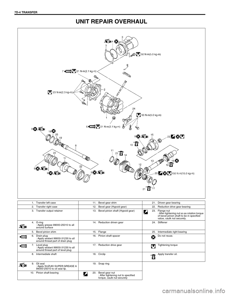
UNIT REPAIR OVERHAUL
1. Transfer left case 11. Bevel gear shim 21. Driven gear bearing
2. Transfer right case 12. Bevel gear (Hypoid gear) 22. Reduction drive gear bearing
3. Transfer output retainer 13. Bevel pinion shaft (Hypoid gear) 23. Flange nut
: After tightening nut so as rotation torque
of bevel pinion shaft to be in specified
value, caulk nut securely.
4. O-ring
: Apply grease 99000-25010 to all
around surface14. Reduction driven gear 24. Stiffener
5. Bevel pinion shim 15. Flange 25. Intermediate right bearing
6. Drain plug
: Apply sealant 99000-31230 to all
around thread part of drain plug16. Pinion shaft spacer Do not reuse.
7. Level plug
: Apply sealant 99000-31230 to all
around thread part of level plug17. Reduction drive gear Tightening torque
8. Intermediate shaft 18. Circlip Apply transfer oil.
9. Oil seal
: Apply SUZUKI SUPER GREASE A
99000-25010 to oil seal lip.19. Snap ring
10. Pinion shaft bearing 20. Bevel gear nut
: After tightening nut to specified
torque, caulk nut securely
Page 219 of 447
TRANSFER 7D-21
Tighten mounting bolt and mounting bracket bolts and nuts
to specified torque.
Tightening torque
Transfer rear mounting bracket nuts
(a) : 50 N·m (5.0 kg-m, 36.5 lb-ft)
Transfer mounting bolt
(b) : 55 N·m (5.5 kg-m, 40.0 lb-ft)
Transfer rear mounting bracket No.2 bolts
(c) : 55 N·m (5.5 kg-m, 40.0 lb-ft)
Tighten transfer stiffener bolts (4) to specified torque.
Tightening torque
Transfer stiffener bolts (a) : 50 N·m (5.0 kg-m, 36.5 lb-ft)
Tighten exhaust pipe bolts.
Tightening torque
Exhaust pipe bolts
(a) : 50 N·m (5.0 kg-m, 36.5 lb-ft)
Install right side drive shaft, refer to Section 4A.
Install propeller shaft and tighten propeller shaft bolts and
center support bolts to specified torque (refer to Section 4B).
Fill gear oil to transfer as specified, refer to OIL CHANGE of
ON-VEHICLE SERVICE.
Check oil level and leakage.
(a)
(b)
(c)
1. Transmission
2. Transfer
3. Stiffener
1. Exhaust No.1 pipe
2. Exhaust No.2 pipe
1
(a)(a)2
Page 220 of 447
7D-22 TRANSFER
TIGHTENING TORQUE SPECIFICATION
REQUIRED SERVICE MATERIAL
SPECIAL TOOL
Fastening partTightening torque
Nm kg-m lb-ft
Transfer oil level/filler and drain plugs 21 2.1 15.5
Transfer bevel gear nut 150 15.0 108.5
Transfer case bolts 23 2.3 17.0
Transfer output retainer bolts 50 5.0 36.5
Transfer mounting bolts 50 5.0 36.5
Transfer rear mounting bracket bolts 55 5.5 40.0
Transfer rear mounting bracket nuts 50 5.5 36.5
Transfer mounting bolt 55 5.5 40.0
Transfer rear mounting bracket No.2 bolts 55 5.5 40.0
Transfer stiffener bolts 50 5.0 36.5
Exhaust pipe bolts 50 5.0 36.5
MaterialRecommended SUZUKI products
(Part Number)Use
Lithium grease SUZUKI SUPER GREASE A
(99000-25010)Oil seal lips
Sealant SUZUKI BOND NO. 1216B
(99000-31230)Oil drain plug
Oil level plug
Mating surface of transfer case
09913-65135 09925-58210 09941-54911 09924-84510-005
Bearing puller Oil seal installer Bearing outer race
removerBearing installer attach-
ment
Page 225 of 447
REAR DIFFERENTIAL 7F-3
DIAGNOSIS
Condition Possible Cause Correction
Gear noise
Deteriorated or water mixed lubricant Repair and replenish.
Inadequate or insufficient lubricant Repair and replenish.
Maladjusted backlash between bevel pinion
and gearAdjust and prescribed.
Improper tooth contact in the mesh between
bevel pinion and gearAdjust or replace.
Loose bevel gear securing bolts Replace or retighten.
Damaged side gear(s) or side pinion(s) Replace.
Bearing noise
(Constant noise) Deteriorated or water mixed
lubricantRepair or replenish.
(Constant noise) Inadequate or insufficient
lubricantRepair or replenish.
(Noise while coasting) Damaged bearing(s) of
bevel pinionReplace.
(Noise while turning) Damaged differential side
bearing(s)Replace.
Oil leakage
Clogged breather plug Clean.
Worn or damaged oil seal Replace.
Excessive oil Adjust oil level.
Page 226 of 447

7F-4 REAR DIFFERENTIAL
ON-VEHICLE SERVICE
OIL CHANGE
1) Before oil change or inspection, be sure to stop engine and
set vehicle horizontally.
2) Check oil level and existence of leakage. If leakage is found,
correct its cause.
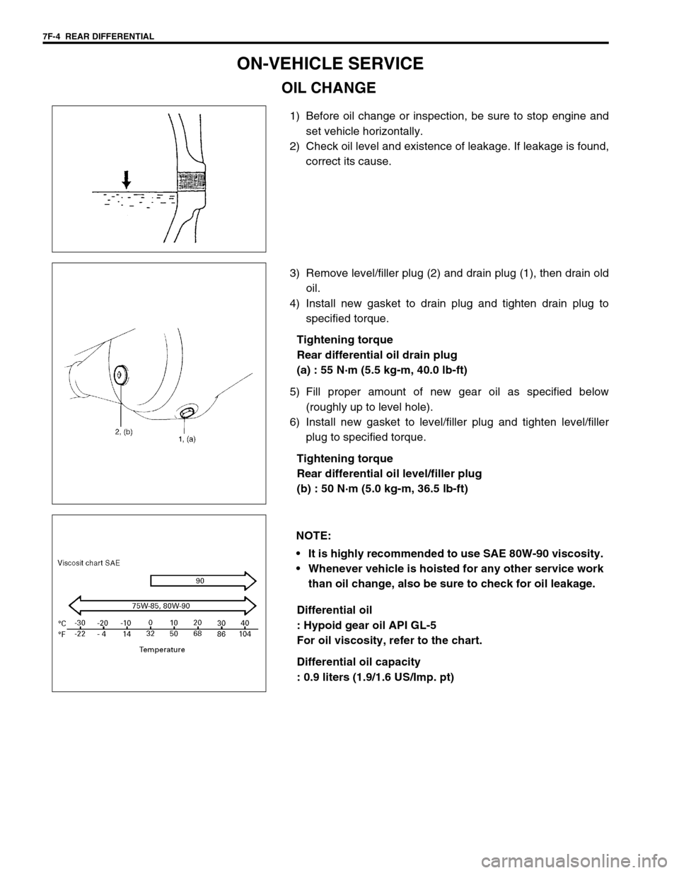
3) Remove level/filler plug (2) and drain plug (1), then drain old
oil.
4) Install new gasket to drain plug and tighten drain plug to
specified torque.
Tightening torque
Rear differential oil drain plug
(a) : 55 N·m (5.5 kg-m, 40.0 lb-ft)
5) Fill proper amount of new gear oil as specified below
(roughly up to level hole).
6) Install new gasket to level/filler plug and tighten level/filler
plug to specified torque.
Tightening torque
Rear differential oil level/filler plug
(b) : 50 N·m (5.0 kg-m, 36.5 lb-ft)
Differential oil
: Hypoid gear oil API GL-5
For oil viscosity, refer to the chart.
Differential oil capacity
: 0.9 liters (1.9/1.6 US/Imp. pt)
NOTE:
It is highly recommended to use SAE 80W-90 viscosity.
Whenever vehicle is hoisted for any other service work
than oil change, also be sure to check for oil leakage.
Page 228 of 447
7F-6 REAR DIFFERENTIAL
DIFFERENTIAL UNIT
DISMOUNTING
1) Hoist vehicle and remove wheels.
2) Drain oil from rear differential. (Refer to “OIL CHANGE” in
this section.)
3) Remove brake drum and disconnect parking brake cable
from brake back plate.
4) Remove axle shafts, refer to “REAR AXLE SHAFT AND
WHEEL BEARING REMOVAL” in Section 3E.
5) Before removing propeller shaft, give match marks (1) on
joint flange and propeller shaft as shown.
6) Remove differential carrier bolts and differential assembly
with viscous coupling case.
1. Drain plug
2. Level plug
1