Page 349 of 557
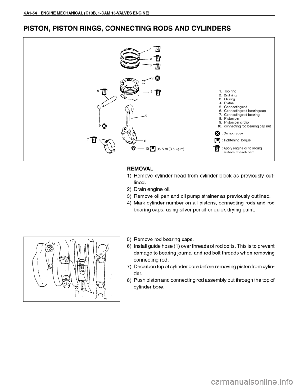
1. Top ring
2. 2nd ring
3. Oil ring
4. Piston
5. Connecting rod
6. Connecting rod bearing cap
7. Connecting rod bearing
8. Piston pin
9. Piston pin circlip
10. connecting rod bearing cap nut
: Do not reuse
: Tightening Torque
: Apply engine oil to sliding
: surface of each part.
6
10
6A1-54 ENGINE MECHANICAL (G13B, 1-CAM 16-VALVES ENGINE)
PISTON, PISTON RINGS, CONNECTING RODS AND CYLINDERS
REMOVAL
1) Remove cylinder head from cylinder block as previously out-
lined.
2) Drain engine oil.
3) Remove oil pan and oil pump strainer as previously outlined.
4) Mark cylinder number on all pistons, connecting rods and rod
bearing caps, using silver pencil or quick drying paint.
5) Remove rod bearing caps.
6) Install guide hose (1) over threads of rod bolts. This is to prevent
damage to bearing journal and rod bolt threads when removing
connecting rod.
7) Decarbon top of cylinder bore before removing piston from cylin-
der.
8) Push piston and connecting rod assembly out through the top of
cylinder bore.
Page 350 of 557
ENGINE MECHANICAL (G13B, 1-CAM 16-VALVES ENGINE) 6A1-55
DISASSEMBLY
1) Using piston ring expander, remove two compression rings (Top
and 2nd) and oil ring from piston.
2) Remove piston pin from connecting rod.
�Ease out piston pin circlips (1), as shown.
�Force piston pin out.
CLEANING
Clean carbon from piston head and ring grooves, using a suitable
tool.
Page 356 of 557
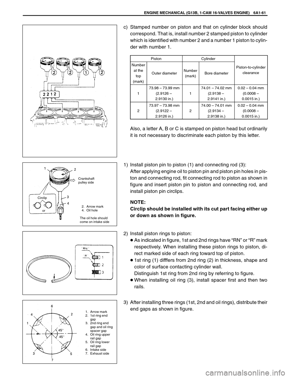
2. Arrow mark
4. Oil hole
The oil hole should
come on intake side
1. Arrow mark
2. 1st ring end
gap
3. 2nd ring end
gap and oil ring
spacer gap
4. Oil ring upper
rail gap
5. Oil ring lower
rail gap
6. Intake side
7. Exhaust side Crankshaft
pulley side
Circlip
or
ENGINE MECHANICAL (G13B, 1-CAM 16-VALVES ENGINE) 6A1-61
c) Stamped number on piston and that on cylinder block should
correspond. That is, install number 2 stamped piston to cylinder
which is identified with number 2 and a number 1 piston to cylin-
der with number 1.
PistonCylinder
Number
at the
top
(mark)
Outer diameterNumber
(mark)Bore diameter
Piston-to-cylinder
clearance
1
73.98 – 73.99 mm
(2.9126 –
2.9130 in.)
1
74.01 – 74.02 mm
(2.9138 –
2.9141 in.)0.02 – 0.04 mm
(0.0008 –
0.0015 in.)
2
73.97 – 73.98 mm
(2.9122 –
2.9126 in.)
2
74.00 – 74.01 mm
(2.9134 –
2.9138 in.)0.02 – 0.04 mm
(0.0008 –
0.0015 in.)
Also, a letter A, B or C is stamped on piston head but ordinarily
it is not necessary to discriminate each piston by this letter.
1) Install piston pin to piston (1) and connecting rod (3):
After applying engine oil to piston pin and piston pin holes in pis-
ton and connecting rod, fit connecting rod to piston as shown in
figure and insert piston pin to piston and connecting rod, and
install piston pin circlips.
NOTE:
Circlip should be installed with its cut part facing either up
or down as shown in figure.
2) Install piston rings to piston:
�As indicated in figure, 1st and 2nd rings have “RN” or “R” mark
respectively. When installing these piston rings to piston, di-
rect marked side of each ring toward top of piston.
�1st ring (1) difffers from 2nd ring (2) in thickness, shape and
color of surface contacting cylinder wall.
Distinguish 1st ring from 2nd ring by referring to figure.
�When installing oil ring (3), install spacer first and then two
rails.
3) After installing three rings (1st, 2nd and oil rings), distribute their
end gaps as shown in figure.
