2000 SUZUKI SWIFT brakes
[x] Cancel search: brakesPage 325 of 698

5-52 BRAKES
Page 330 of 698

ANTILOCK BRAKE SYSTEM (ABS) 5E-5
ABS HYDRAULIC UNIT/CONTROL MODULE
ASSEMBLY
ABS control module is a component of ABS hydraulic unit/control
module assembly and has the following functions.
SELF-DIAGNOSIS FUNCTION
ABS control module diagnoses conditions of the system compo-
nent parts (whether or not there is any abnormality) all the time
and indicates the results (warning of abnormality occurrence and
DTC) through the ABS warning lamp as described below.
1) When ignition switch is turned ON, ABS warning lamp lights
for 2 seconds to check its bulb and circuit.
2) When no abnormality has been detected (the system is in
good condition), ABS warning lamp turns OFF after 2 sec-
onds.
3) When an abnormality in the system is detected, ABS warn-
ing lamp lights and the area where that abnormality lies is
stored in the memory of EEPROM in ABS control module.
4) When Diag. switch terminal (2) of diagnosis connector (1)
(monitor connector) is grounded, the abnormal area is output
as DTC. It is indicated by flashing of ABS warning lamp.
(Refer to the table below.)
5) For procedure to clear all DTC’s, refer to “DIAGNOSTIC
TROUBLE CODE CLEARANCE” in this section.
Also ABS control module turns ON EBD warning lamp (brake
warning lamp) depending on the trouble that detected by the
module and EBD warning lamp does not indicate DTC as well as
ABS warning lamp.
FAIL-SAFE FUNCTION
When an abnormality occurs (an abnormal DTC is detected),
ABS control module turns OFF the fail-safe relay which supplies
power to ABS hydraulic unit. Thus, with ABS not operating,
brakes function just like the brake system of the vehicle without
ABS.
SYSTEM CONDITIONABS WARNING LAMP
Diag. switch
terminal is
not groundedDiag. switch
terminal is
grounded
In good
condition
at presentNo trouble in the past OFF DTC 12
Trouble occurred in
the pastOFF History DTC
Abnormal-
ity exists
at presentNo trouble in the past ON Current DTC
Trouble occurred in
the pastONCurrent and
history DTCs
3. Ground terminal
4. Service wire
3 11
2
4
Page 334 of 698

ANTILOCK BRAKE SYSTEM (ABS) 5E-9
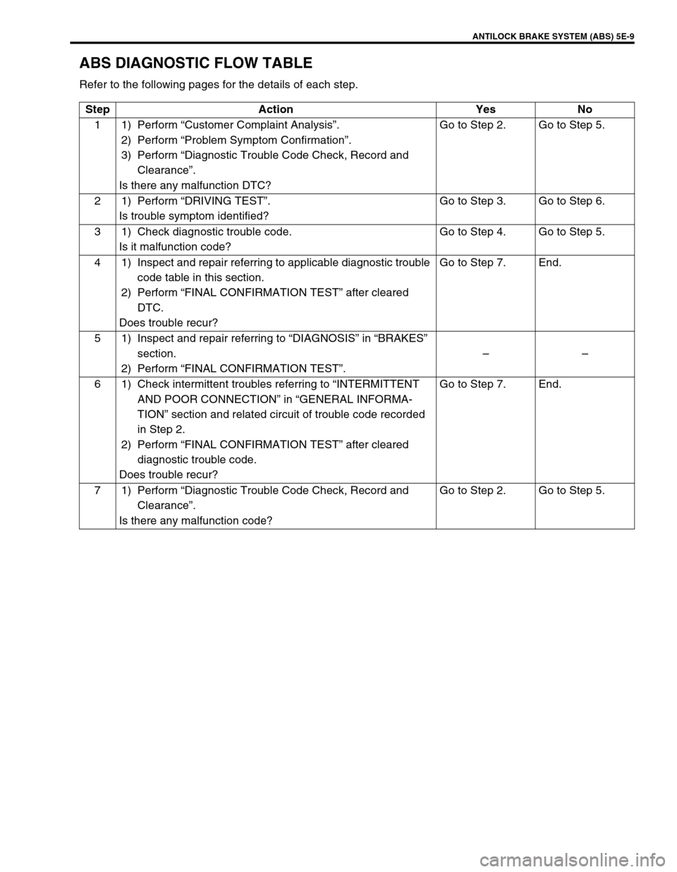
ABS DIAGNOSTIC FLOW TABLE
Refer to the following pages for the details of each step.
Step Action Yes No
11)Perform “Customer Complaint Analysis”.
2) Perform “Problem Symptom Confirmation”.
3) Perform “Diagnostic Trouble Code Check, Record and
Clearance”.
Is there any malfunction DTC?Go to Step 2. Go to Step 5.
21)Perform “DRIVING TEST”.
Is trouble symptom identified?Go to Step 3. Go to Step 6.
3 1) Check diagnostic trouble code.
Is it malfunction code?Go to Step 4. Go to Step 5.
4 1) Inspect and repair referring to applicable diagnostic trouble
code table in this section.
2) Perform “FINAL CONFIRMATION TEST” after cleared
DTC.
Does trouble recur?Go to Step 7. End.
5 1) Inspect and repair referring to “DIAGNOSIS” in “BRAKES”
section.
2) Perform “FINAL CONFIRMATION TEST”.––
6 1) Check intermittent troubles referring to “INTERMITTENT
AND POOR CONNECTION” in “GENERAL INFORMA-
TION” section and related circuit of trouble code recorded
in Step 2.
2) Perform “FINAL CONFIRMATION TEST” after cleared
diagnostic trouble code.
Does trouble recur?Go to Step 7. End.
71)Perform “Diagnostic Trouble Code Check, Record and
Clearance”.
Is there any malfunction code?Go to Step 2. Go to Step 5.
Page 336 of 698

ANTILOCK BRAKE SYSTEM (ABS) 5E-11
c) Diagnostic Trouble Code (DTC) Check, Record and Clearance
Perform “DIAGNOSTIC TROUBLE CODE CHECK” procedure in this section, record it and then clear it
referring to “DIAGNOSTIC TROUBLE CODE CLEARANCE” in this section.
If the malfunction DTC which was once displayed and then cleared cannot be detected (indicated) again
when the ignition switch is turned ON, attempt to diagnose the trouble based on the DTC recorded in this
step may mislead the diagnosis or make diagnosing difficult. Proceed to Step 2) to check control module
for proper self-diagnosis function.
If the malfunction DTC which was once displayed and then cleared can be detected (indicated) again when
ignition switch is turned ON, proceed to Step 3).
2) DRIVING TEST
Test drive the vehicle at 40 km/h for more than a minute and check if any trouble symptom (such as abnor-
mal lighting of ABS warning light) exists.
If the malfunction DTC is confirmed again at ignition switch ON, driving test as described in above is not nec-
essary. Proceed to Step 3).
3) DIAGNOSTIC TROUBLE CODE CHECK
Recheck diagnostic trouble code referring to “DTC CHECK” as shown in the following page.
4) DIAGNOSTIC TROUBLE CODE FLOW TABLE
According to Diagnostic flow table for the diagnostic trouble code confirmation in Step 3), locate the cause of
the trouble, namely in a sensor, switch, wire harness, connector, actuator assembly or other part and repair
or replace faulty parts.
5)“DIAGNOSIS” IN “BRAKES” SECTION
Check the parts or system suspected as a possible cause referring to “DIAGNOSIS” in “BRAKES” section
and based on symptoms appearing on the vehicle (symptom obtained through Steps 1)-a, 1)-b and 2) and
repair or replace faulty parts, if any).
6) CHECK FOR INTERMITTENT PROBLEM
Check parts where an intermittent trouble is easy to occur (e.g., wire harness, connector, etc.), referring to
“INTERMITTENT TROUBLE” in “GENERAL INFORMATION” section and related circuit of trouble code
recorded in Step 1)-c.
7) FINAL CONFIRMATION TEST
Confirm that the problem symptom has gone and the ABS is free from any abnormal conditions. If what has
been repaired is related to the malfunction DTC, clear the DTC once and perform test driving and confirm
that no DTC is indicated.
Page 359 of 698

5E-34 ANTILOCK BRAKE SYSTEM (ABS)
3) Using special tool, loosen flare nuts (1) and disconnect
brake pipes (2) from ABS hydraulic unit/control module
assembly (3).
Special tool
09950-78220
4) Remove two nuts and disconnect take out ABS hydraulic
unit/control module assembly (1) from bracket using flat end
rod or the like (2).
INSTALLATION
1) Install hydraulic unit/control module assembly by reversing
removal procedure.
Tightening torque
Brake pipe flare nut (a) :
16 N·m (1.6 kg-m, 11.5 lb-ft)
ABS hydraulic unit/control module assembly bolt (b) :
9 N·m (0.9 kg-m, 6.5 lb-ft)
ABS hydraulic unit/control module assembly bracket bolt
(c) : 26 N·m (2.6 kg-m, 18.0 lb-ft)
2) Bleed air from brake system referring to “BRAKES” section.
3) Check each installed part for fluid leakage and perform “ABS
HYDRAULIC UNIT OPERATION CHECK” in this section. NOTE:
Put bleeder plug cap onto pipe to prevent fluid from spill-
ing. Do not allow brake fluid to get on painted surfaces.
312
CAUTION:
Do not give an impact to hydraulic unit.
Use care not to allow dust to enter hydraulic unit.
Do not place hydraulic unit on its side or upside down.
Handling it in inappropriate way will affect its original
performance.
NOTE:
For new ABS hydraulic unit/control module assembly, if
“ABS HYDRAULIC UNIT OPERATION CHECK” procedure
has not been performed, “ABS” warning lamp may flash
when ignition switch is turned ON position.
Accordingly preform “ABS HYDRAULIC UNIT OPERA-
TION CHECK” to stop flashing of ABS warning lamp.
(b)
(c) (b)(a)
Page 396 of 698

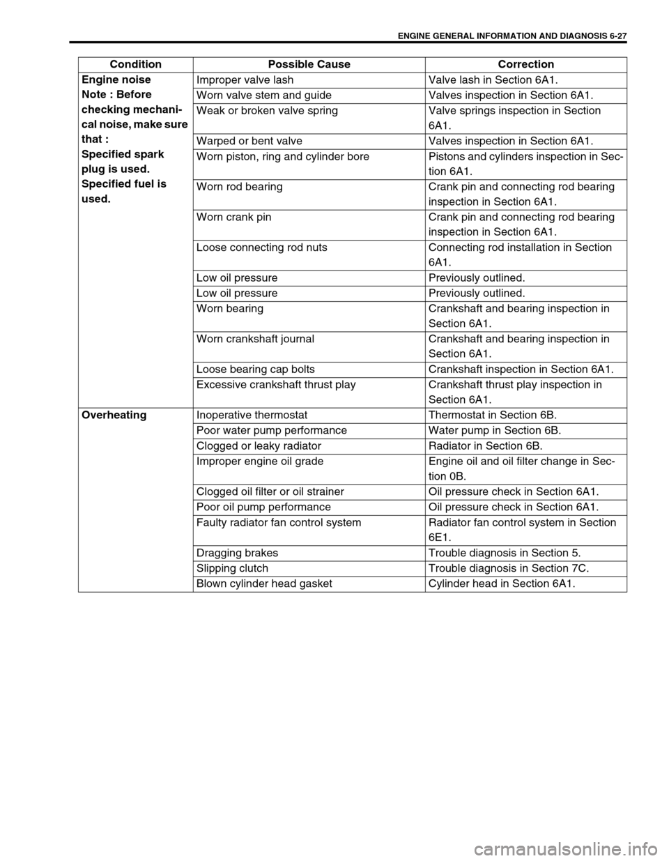
ENGINE GENERAL INFORMATION AND DIAGNOSIS 6-27
Engine noise
Note : Before
checking mechani-
cal noise, make sure
that :
Specified spark
plug is used.
Specified fuel is
used.Improper valve lash Valve lash in Section 6A1.
Worn valve stem and guide Valves inspection in Section 6A1.
Weak or broken valve spring Valve springs inspection in Section
6A1.
Warped or bent valve Valves inspection in Section 6A1.
Worn piston, ring and cylinder bore Pistons and cylinders inspection in Sec-
tion 6A1.
Worn rod bearing Crank pin and connecting rod bearing
inspection in Section 6A1.
Worn crank pin Crank pin and connecting rod bearing
inspection in Section 6A1.
Loose connecting rod nuts Connecting rod installation in Section
6A1.
Low oil pressure Previously outlined.
Low oil pressure Previously outlined.
Worn bearing Crankshaft and bearing inspection in
Section 6A1.
Worn crankshaft journal Crankshaft and bearing inspection in
Section 6A1.
Loose bearing cap bolts Crankshaft inspection in Section 6A1.
Excessive crankshaft thrust play Crankshaft thrust play inspection in
Section 6A1.
Overheating
Inoperative thermostat Thermostat in Section 6B.
Poor water pump performance Water pump in Section 6B.
Clogged or leaky radiator Radiator in Section 6B.
Improper engine oil grade Engine oil and oil filter change in Sec-
tion 0B.
Clogged oil filter or oil strainer Oil pressure check in Section 6A1.
Poor oil pump performance Oil pressure check in Section 6A1.
Faulty radiator fan control system Radiator fan control system in Section
6E1.
Dragging brakes Trouble diagnosis in Section 5.
Slipping clutch Trouble diagnosis in Section 7C.
Blown cylinder head gasket Cylinder head in Section 6A1. Condition Possible Cause Correction
Page 397 of 698

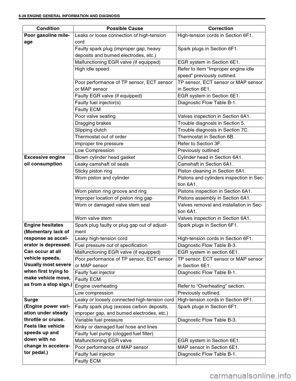
6-28 ENGINE GENERAL INFORMATION AND DIAGNOSIS
Poor gasoline mile-
age Leaks or loose connection of high-tension
cordHigh-tension cords in Section 6F1.
Faulty spark plug (improper gap, heavy
deposits and burned electrodes, etc.)Spark plugs in Section 6F1.
Malfunctioning EGR valve (if equipped) EGR system in Section 6E1.
High idle speed Refer to item “Improper engine idle
speed” previously outlined.
Poor performance of TP sensor, ECT sensor
or MAP sensorTP sensor, ECT sensor or MAP sensor
in Section 6E1.
Faulty EGR valve (if equipped) EGR system in Section 6E1.
Faulty fuel injector(s) Diagnostic Flow Table B-1.
Faulty ECM
Poor valve seating Valves inspection in Section 6A1.
Dragging brakes Trouble diagnosis in Section 5.
Slipping clutch Trouble diagnosis in Section 7C.
Thermostat out of order Thermostat in Section 6B.
Improper tire pressure Refer to Section 3F.
Low Compression Previously outlined
Excessive engine
oil consumption Blown cylinder head gasket Cylinder head in Section 6A1.
Leaky camshaft oil seals Camshaft in Section 6A1.
Sticky piston ring Piston cleaning in Section 6A1.
Worn piston and cylinder Pistons and cylinders inspection in Sec-
tion 6A1.
Worn piston ring groove and ring Pistons inspection in Section 6A1.
Improper location of piston ring gap Pistons assembly in Section 6A1.
Worn or damaged valve stem seal Valves removal and installation in Sec-
tion 6A1.
Worn valve stem Valves inspection in Section 6A1.
Engine hesitates
(Momentary lack of
response as accel-
erator is depressed.
Can occur at all
vehicle speeds.
Usually most severe
when first trying to
make vehicle move,
as from a stop sign.)Spark plug faulty or plug gap out of adjust-
mentSpark plugs in Section 6F1.
Leaky high-tension cord High-tension cords in Section 6F1.
Fuel pressure out of specification Diagnostic Flow Table B-3.
Malfunctioning EGR valve (if equipped) EGR system in section 6E1.
Poor performance of TP sensor, ECT sensor
or MAP sensorTP sensor, ECT sensor or MAP sensor
in Section 6E1.
Faulty fuel injector Diagnostic Flow Table B-1.
Faulty ECM
Engine overheating Refer to “Overheating” section.
Low compression Previously outlined.
Surge
(Engine power vari-
ation under steady
throttle or cruise.
Feels like vehicle
speeds up and
down with no
change in accelera-
tor pedal.)Leaky or loosely connected high-tension cord High-tension cords in Section 6F1.
Faulty spark plug (excess carbon deposits,
improper gap, and burned electrodes, etc.)Spark plugs in Section 6F1.
Variable fuel pressure Diagnostic Flow Table B-3.
Kinky or damaged fuel hose and lines
Faulty fuel pump (clogged fuel filter)
Malfunctioning EGR valve EGR system in Section 6E1.
Poor performance of MAP sensor MAP sensor in Section 6E1.
Faulty fuel injector Diagnostic Flow Table B-1.
Faulty ECM Condition Possible Cause Correction
Page 398 of 698

ENGINE GENERAL INFORMATION AND DIAGNOSIS 6-29
Excessive detona-
tion
(Engine makes con-
tinuously sharp
metallic knocks that
change with throttle
opening. Sounds
like pop corn pop-
ping.)Faulty spark plug Spark plugs in Section 6F1.
Loose connection of high-tension cord High-tension cords in Section 6F1.
Engine overheating Refer to “Overheating” section.
Clogged fuel filter (faulty fuel pump) or fuel
linesDiagnostic Flow Table B-1 or B-2.
Air inhaling from intake manifold or throttle
body gasket
Malfunctioning EGR valve (if equipped) EGR system in Section 6E1.
Poor performance of knock sensor, ECT sen-
sor or MAP sensorKnock sensor in Section 6, ECT sensor
or MAP sensor in Section 6E1.
Faulty fuel injector(s) Diagnostic Flow Table B-1.
Faulty ECM
Excessive combustion chamber deposits Piston and cylinder head cleaning in
Section 6A1.
Engine has no
powerFaulty spark plug Spark plugs in Section 6F1.
Faulty ignition coil with ignitor Ignition coil in Section 6F1.
Leaks, loose connection or disconnection of
high-tension cordHigh-tension cords in Section 6F1.
Faulty knock sensor Knock sensor malfunction in this sec-
tion.
Clogged fuel hose or pipe Diagnostic Flow Table B-3.
Malfunctioning fuel pump Diagnostic Flow Table B-2.
Air inhaling from intake manifold gasket or
throttle body gasket
Engine overheating Refer to “Overheating” section.
Engine has no
powerMalfunctioning EGR valve (if equipped) EGR system inspection in Section 6E1.
Maladjusted accelerator cable play Accelerator cable play in Section 6E1.
Poor performance of TP sensor, ECT sensor
or MAP sensorTP sensor, ECT sensor or MAP sensor
in Section 6E1.
Faulty fuel injector(s) Diagnostic Flow Table B-1.
Faulty ECM
Dragging brakes Trouble diagnosis in Section 5.
Slipping clutch Trouble diagnosis in Section 7C.
Low compression Previously outlined. Condition Possible Cause Correction