Page 317 of 698
5-44 BRAKES
REAR BRAKE HOSE/PIPE
REMOVAL
1) Raise and support vehicle properly. Remove tire and wheel.
2) Clean dirt and foreign material from both flexible hose end and pipe end fittings.
3) Remove brake flexible hose or pipe.
INSTALLATION
Reverse brake flexible hose installation procedure, nothing the followings.
Fill and maintain brake fluid level in reservoir.
Bleed brake system. Refer to “AIR BLEEDING OF BRAKE SYSTEM”.
Perform brake test and check each installed part for fluid leakage.
Never reuse protector nut once removed. Be sure to use a new one.
Install clamps properly referring to figure below and tighten bolts.
When installing hose, make sure that it has no twist or kink.
Page 318 of 698
BRAKES 5-45
T : Top side 1. 4 way joint [A] : with ABS
F : Front side 2. LSPV assembly [B] : without ABS
R : Right side 3. P valve [C] : with LSPV
L : Left side 4. Rear brake hose Tightening torque
B : View B a-g: Clamp
Page 319 of 698
5-46 BRAKES
PARKING BRAKE CABLE
REMOVAL
1) Raise, suitably support vehicle and remove wheel.
2) Remove parking brake cable.
INSTALLATION
Install it by reversing removal procedure, noting the following points.
Install clamps properly referring to figure below.
Tighten bolts and nuts to specified torque.
Adjust parking brake cable. (Refer to “PARKING BRAKE INSPECTION AND ADJUSTMENT”.)
Check brake drum for dragging and brake system for proper performance. After removing vehicle from hoist,
brake test should be performed.
Page 320 of 698
BRAKES 5-47
T : Top side 3. Inner cable end a : View A f : View F
F : Front side 4. Spring b : View B Tightening torque
R : Rear side 5. Adjusting nut c : View C
1. Cable
: Apply water tight sealant (99000-31090)6. Clip d : View D
2. Parking brake shoe lever 7. Parking brake lever e : View E
Page 321 of 698
5-48 BRAKES
LSPV (LOAD SENSING PROPORTIONING VALVE) ASSEMBLY (IF EQUIPPED)
REMOVAL
1) Clean around reservoir cap and take out fluid with syringe or
such.
2) Hoist vehicle.
3) Disconnect brake pipes from LSPV assembly.
Special tool
09950-78230 (10 x 11 mm)
4) Remove nut (2) and detach spring end from rear axle (3).
5) Remove LSPV assembly (1) with spring (4) from vehicle
body.
1. LSPV assembly 3. Adjust nut Tightening torque
2. Spring 4. Brake pipe
CAUTION:
Never disassemble LSPV assembly. Disassembly will
spoil its original performance. Replace with new one if
detective.
3
21
25 N·m(2.5 kg-m)
4 16 N·m(1.6 kg-m)
25 N·m(2.5 kg-m)
3
24
1
Page 322 of 698

BRAKES 5-49
INSTALLATION
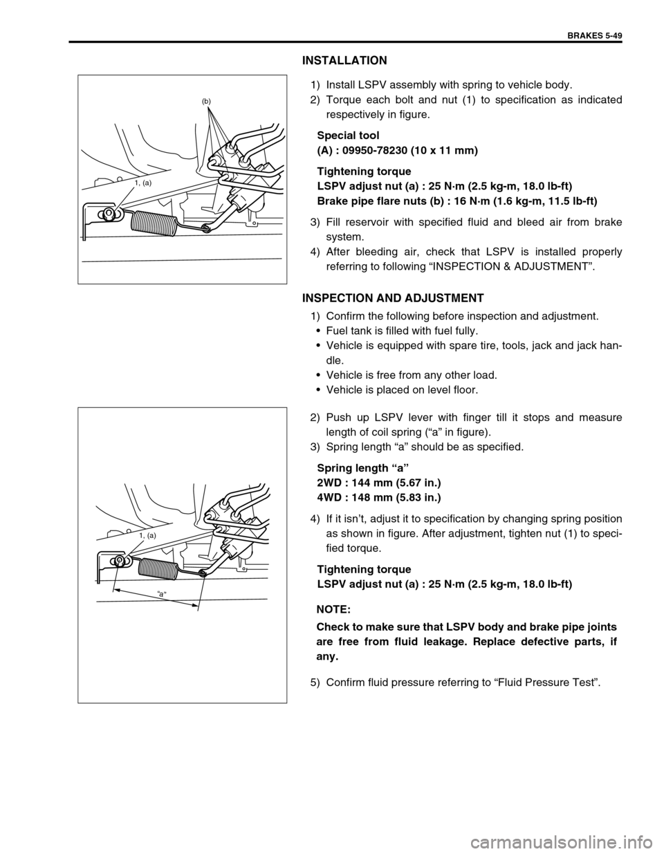
1) Install LSPV assembly with spring to vehicle body.
2) Torque each bolt and nut (1) to specification as indicated
respectively in figure.
Special tool
(A) : 09950-78230 (10 x 11 mm)
Tightening torque
LSPV adjust nut (a) : 25 N·m (2.5 kg-m, 18.0 lb-ft)
Brake pipe flare nuts (b) : 16 N·m (1.6 kg-m, 11.5 lb-ft)
3) Fill reservoir with specified fluid and bleed air from brake
system.
4) After bleeding air, check that LSPV is installed properly
referring to following “INSPECTION & ADJUSTMENT”.
INSPECTION AND ADJUSTMENT
1) Confirm the following before inspection and adjustment.
Fuel tank is filled with fuel fully.
Vehicle is equipped with spare tire, tools, jack and jack han-
dle.
Vehicle is free from any other load.
Vehicle is placed on level floor.
2) Push up LSPV lever with finger till it stops and measure
length of coil spring (“a” in figure).
3) Spring length “a” should be as specified.
Spring length “a”
2WD : 144 mm (5.67 in.)
4WD : 148 mm (5.83 in.)
4) If it isn’t, adjust it to specification by changing spring position
as shown in figure. After adjustment, tighten nut (1) to speci-
fied torque.
Tightening torque
LSPV adjust nut (a) : 25 N·m (2.5 kg-m, 18.0 lb-ft)
5) Confirm fluid pressure referring to “Fluid Pressure Test”.
1, (a)
(b)
NOTE:
Check to make sure that LSPV body and brake pipe joints
are free from fluid leakage. Replace defective parts, if
any.
1, (a)
“a”
Page 323 of 698
5-50 BRAKES
REQUIRED SERVICE MATERIAL
SPECIAL TOOL
MaterialRecommended SUZUKI product
(Part Number)Use
Brake fluid DOT 3 or SAE J1703To fill master cylinder reservoir.
To clean and apply to inner parts of master
cylinder caliper and wheel cylinder when they
are disassembled.
Water tight sealant SEALING COMPOUND 366E
(99000-31090)To apply to mating surfaces of brake back
plate and rear axle (2WD vehicle) or rear
axle housing (4WD vehicle).
To apply to mating surfaces of brake back
plate and parking brake cable.
Lithium grease SUZUKI SUPER GREASE A
(99000-25010)To apply to slide pin of brake caliper carrier.
09900-06106 09900-20606 09900-20701 09942-15510
Snap ring remover Dial gauge Dial gauge chuck Sliding hammer
09943-17912 09951-18220 09952-16020 09952-46010
Brake drum remover
(Front wheel hub
remover)Secondary cup installer
setBooster piston rod
adjusterMaster cylinder attach-
ment
Page 324 of 698
BRAKES 5-51
09950-96010 09956-02310 09950-78230 09952-48320
Booster piston rod gauge Fluid pressure gauge Flare nut wrench
(10 x 11 mm)Pressure gauge attach-
ment
09952-26020
Master cylinder plug