2000 SUZUKI SWIFT Exhaust
[x] Cancel search: ExhaustPage 573 of 698
6A1-72 ENGINE MECHANICAL (M13 ENGINE)
6) Install generator referring to Section 6H.
7) For 4WD vehicle, install propeller shaft referring to Section
4B.
8) Connect drive shaft joints referring to Section 4.
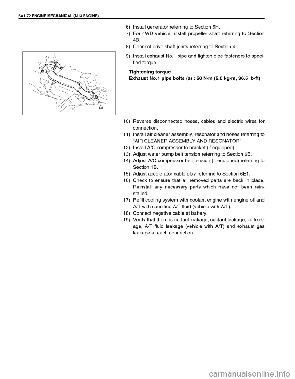
9) Install exhaust No.1 pipe and tighten pipe fasteners to speci-
fied torque.
Tightening torque
Exhaust No.1 pipe bolts (a) : 50 N·m (5.0 kg-m, 36.5 lb-ft)
10) Reverse disconnected hoses, cables and electric wires for
connection.
11) Install air cleaner assembly, resonator and hoses referring to
“AIR CLEANER ASSEMBLY AND RESONATOR”
12) Install A/C compressor to bracket (if equipped).
13) Adjust water pump belt tension referring to Section 6B.
14) Adjust A/C compressor belt tension (if equipped) referring to
Section 1B.
15) Adjust accelerator cable play referring to Section 6E1.
16) Check to ensure that all removed parts are back in place.
Reinstall any necessary parts which have not been rein-
stalled.
17) Refill cooling system with coolant engine with engine oil and
A/T with specified A/T fluid (vehicle with A/T).
18) Connect negative cable at battery.
19) Verify that there is no fuel leakage, coolant leakage, oil leak-
age, A/T fluid leakage (vehicle with A/T) and exhaust gas
leakage at each connection.
Page 575 of 698
6A1-74 ENGINE MECHANICAL (M13 ENGINE)
REMOVAL
1) Remove engine assembly from vehicle as previously out-
lined.
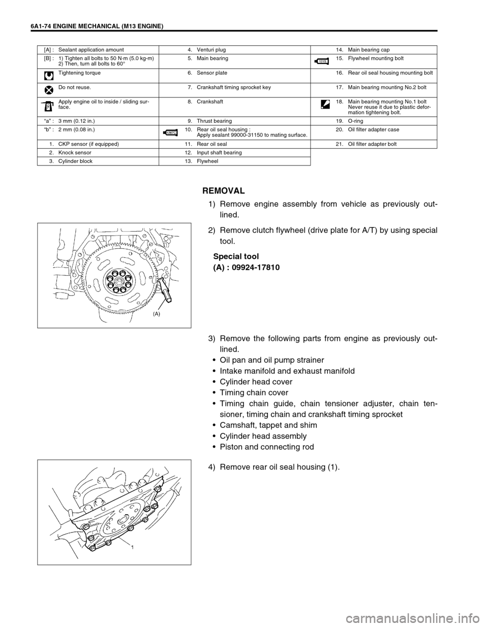
2) Remove clutch flywheel (drive plate for A/T) by using special
tool.
Special tool
(A) : 09924-17810
3) Remove the following parts from engine as previously out-
lined.
Oil pan and oil pump strainer
Intake manifold and exhaust manifold
Cylinder head cover
Timing chain cover
Timing chain guide, chain tensioner adjuster, chain ten-
sioner, timing chain and crankshaft timing sprocket
Camshaft, tappet and shim
Cylinder head assembly
Piston and connecting rod
4) Remove rear oil seal housing (1).
[A] : Sealant application amount 4. Venturi plug 14. Main bearing cap
[B] : 1) Tighten all bolts to 50 N·m (5.0 kg-m)
2) Then, turn all bolts to 60°5. Main bearing 15. Flywheel mounting bolt
Tightening torque 6. Sensor plate 16. Rear oil seal housing mounting bolt
Do not reuse. 7. Crankshaft timing sprocket key 17. Main bearing mounting No.2 bolt
Apply engine oil to inside / sliding sur-
face.8. Crankshaft
18. Main bearing mounting No.1 bolt
Never reuse it due to plastic defor-
mation tightening bolt.
“a” : 3 mm (0.12 in.) 9. Thrust bearing 19. O-ring
“b” : 2 mm (0.08 in.) 10. Rear oil seal housing :
Apply sealant 99000-31150 to mating surface.20. Oil filter adapter case
1. CKP sensor (if equipped) 11. Rear oil seal 21. Oil filter adapter bolt
2. Knock sensor 12. Input shaft bearing
3. Cylinder block 13. Flywheel
Page 586 of 698
ENGINE MECHANICAL (M13 ENGINE) 6A1-85
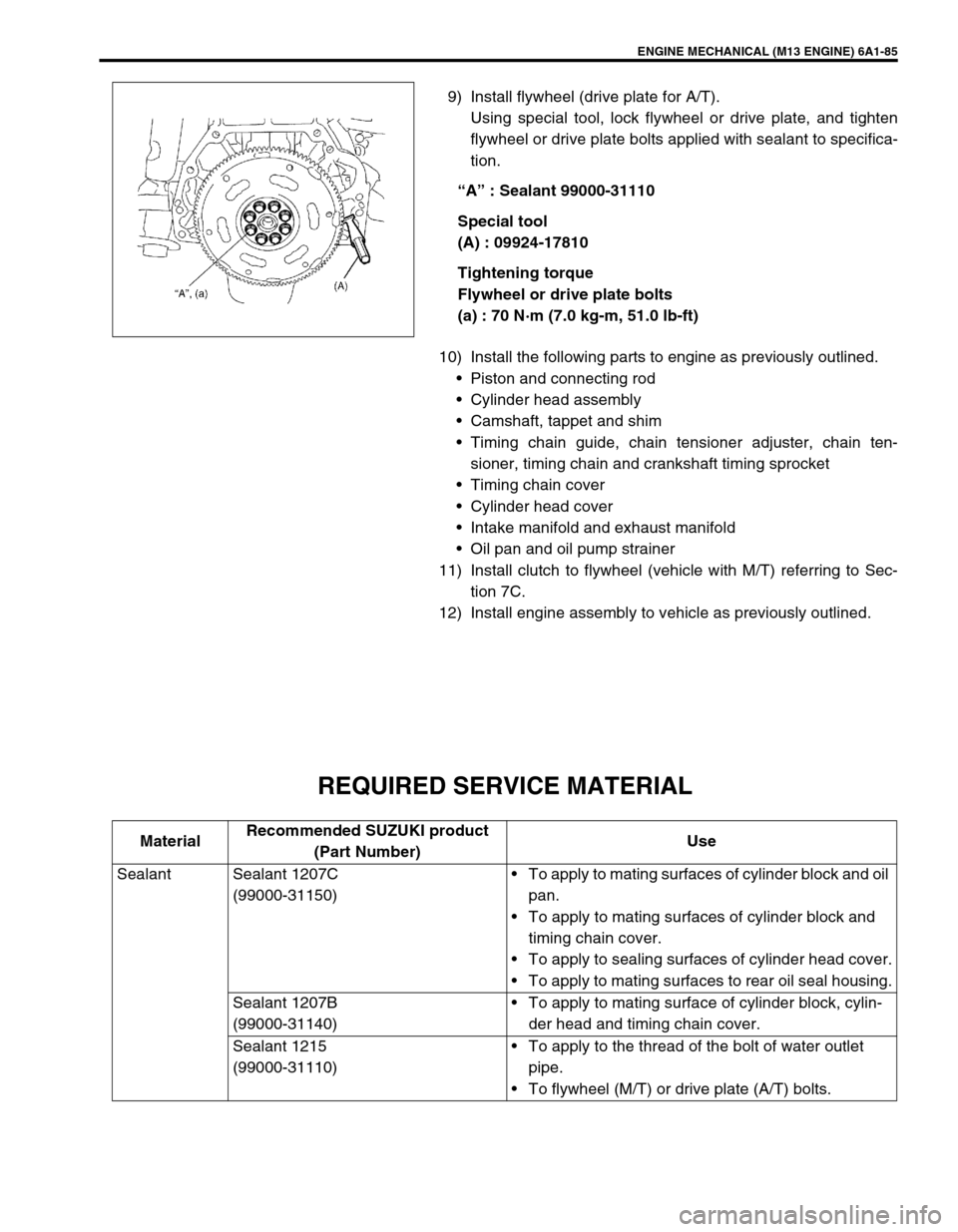
9) Install flywheel (drive plate for A/T).
Using special tool, lock flywheel or drive plate, and tighten
flywheel or drive plate bolts applied with sealant to specifica-
tion.
“A” : Sealant 99000-31110
Special tool
(A) : 09924-17810
Tightening torque
Flywheel or drive plate bolts
(a) : 70 N·m (7.0 kg-m, 51.0 lb-ft)
10) Install the following parts to engine as previously outlined.
Piston and connecting rod
Cylinder head assembly
Camshaft, tappet and shim
Timing chain guide, chain tensioner adjuster, chain ten-
sioner, timing chain and crankshaft timing sprocket
Timing chain cover
Cylinder head cover
Intake manifold and exhaust manifold
Oil pan and oil pump strainer
11) Install clutch to flywheel (vehicle with M/T) referring to Sec-
tion 7C.
12) Install engine assembly to vehicle as previously outlined.
REQUIRED SERVICE MATERIAL
MaterialRecommended SUZUKI product
(Part Number)Use
Sealant Sealant 1207C
(99000-31150)To apply to mating surfaces of cylinder block and oil
pan.
To apply to mating surfaces of cylinder block and
timing chain cover.
To apply to sealing surfaces of cylinder head cover.
To apply to mating surfaces to rear oil seal housing.
Sealant 1207B
(99000-31140)To apply to mating surface of cylinder block, cylin-
der head and timing chain cover.
Sealant 1215
(99000-31110)To apply to the thread of the bolt of water outlet
pipe.
To flywheel (M/T) or drive plate (A/T) bolts.
Page 587 of 698
6A1-86 ENGINE MECHANICAL (M13 ENGINE)
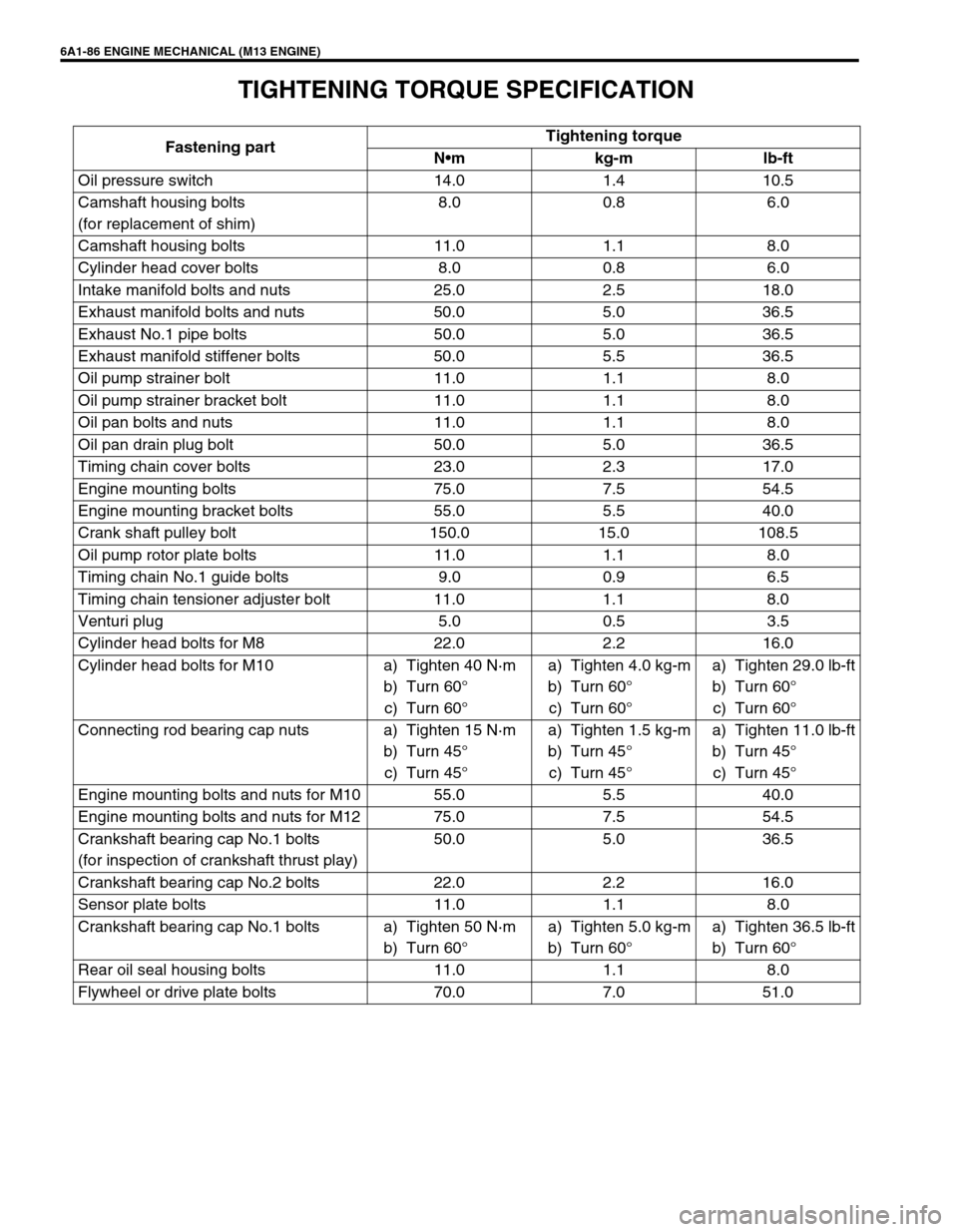
TIGHTENING TORQUE SPECIFICATION
Fastening partTightening torque
Nm kg-m lb-ft
Oil pressure switch 14.0 1.4 10.5
Camshaft housing bolts
(for replacement of shim)8.0 0.8 6.0
Camshaft housing bolts 11.0 1.1 8.0
Cylinder head cover bolts 8.0 0.8 6.0
Intake manifold bolts and nuts 25.0 2.5 18.0
Exhaust manifold bolts and nuts 50.0 5.0 36.5
Exhaust No.1 pipe bolts 50.0 5.0 36.5
Exhaust manifold stiffener bolts 50.0 5.5 36.5
Oil pump strainer bolt 11.0 1.1 8.0
Oil pump strainer bracket bolt 11.0 1.1 8.0
Oil pan bolts and nuts 11.0 1.1 8.0
Oil pan drain plug bolt 50.0 5.0 36.5
Timing chain cover bolts 23.0 2.3 17.0
Engine mounting bolts 75.0 7.5 54.5
Engine mounting bracket bolts 55.0 5.5 40.0
Crank shaft pulley bolt 150.0 15.0 108.5
Oil pump rotor plate bolts 11.0 1.1 8.0
Timing chain No.1 guide bolts 9.0 0.9 6.5
Timing chain tensioner adjuster bolt 11.0 1.1 8.0
Venturi plug 5.0 0.5 3.5
Cylinder head bolts for M8 22.0 2.2 16.0
Cylinder head bolts for M10 a) Tighten 40 N·m
b) Turn 60°
c) Turn 60°a) Tighten 4.0 kg-m
b) Turn 60°
c) Turn 60°a) Tighten 29.0 lb-ft
b) Turn 60°
c) Turn 60°
Connecting rod bearing cap nuts a) Tighten 15 N·m
b) Turn 45°
c) Turn 45°a) Tighten 1.5 kg-m
b) Turn 45°
c) Turn 45°a) Tighten 11.0 lb-ft
b) Turn 45°
c) Turn 45°
Engine mounting bolts and nuts for M10 55.0 5.5 40.0
Engine mounting bolts and nuts for M12 75.0 7.5 54.5
Crankshaft bearing cap No.1 bolts
(for inspection of crankshaft thrust play)50.0 5.0 36.5
Crankshaft bearing cap No.2 bolts 22.0 2.2 16.0
Sensor plate bolts 11.0 1.1 8.0
Crankshaft bearing cap No.1 bolts a) Tighten 50 N·m
b) Turn 60°a) Tighten 5.0 kg-m
b) Turn 60°a) Tighten 36.5 lb-ft
b) Turn 60°
Rear oil seal housing bolts 11.0 1.1 8.0
Flywheel or drive plate bolts 70.0 7.0 51.0
Page 638 of 698
ENGINE AND EMISSION CONTROL SYSTEM 6E1-17
IDLE MIXTURE INSPECTION / ADJUSTMENT (VEHI-
CLE WITHOUT HEATED OXYGEN SENSOR)
All vehicles not equipped with heated oxygen sensor are shipped
with their CO % factory adjusted as follows.
Engine idle mixture (CO %)
0.5 – 1.5 % at specified idle speed
Idle mixture adjustment should never be changed from the origi-
nal factory setting. However, if during diagnosis, the check indi-
cates idle mixture to be the cause of a driver performance
complaint or emission failure, the idle mixture can be adjusted
using the following procedures.
1) Check idle speed according to “Idle Speed Inspection” sec-
tion.
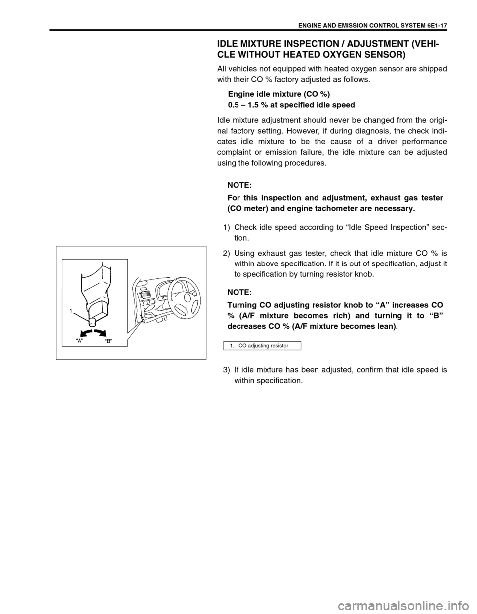
2) Using exhaust gas tester, check that idle mixture CO % is
within above specification. If it is out of specification, adjust it
to specification by turning resistor knob.
3) If idle mixture has been adjusted, confirm that idle speed is
within specification. NOTE:
For this inspection and adjustment, exhaust gas tester
(CO meter) and engine tachometer are necessary.
NOTE:
Turning CO adjusting resistor knob to “A” increases CO
% (A/F mixture becomes rich) and turning it to “B”
decreases CO % (A/F mixture becomes lean).
1. CO adjusting resistor
Page 652 of 698
ENGINE AND EMISSION CONTROL SYSTEM 6E1-31
HEATED OXYGEN SENSOR (HO2S-1 AND HO2S-2)
OXYGEN SENSOR HEATER INSPECTION
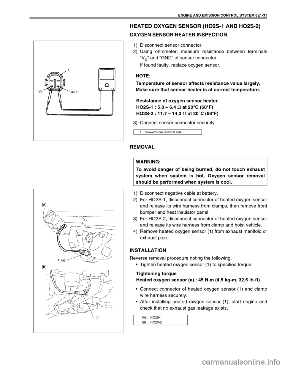
1) Disconnect sensor connector.
2) Using ohmmeter, measure resistance between terminals
“V
B” and “GND” of sensor connector.
If found faulty, replace oxygen sensor.
Resistance of oxygen sensor heater
HO2S-1 : 5.0 – 6.4
Ω at 20°C (68°F)
HO2S-2 : 11.7 – 14.3
Ω at 20°C (68°F)
3) Connect sensor connector securely.
REMOVAL
1) Disconnect negative cable at battery.
2) For HO2S-1, disconnect connector of heated oxygen sensor
and release its wire harness from clamps, then remove front
bumper and heat insulator panel.
3) For HO2S-2, disconnect connector of heated oxygen sensor
and release its wire harness from clamp and hoist vehicle.
4) Remove heated oxygen sensor (1) from exhaust manifold or
exhaust pipe.
INSTALLATION
Reverse removal procedure noting the following.
Tighten heated oxygen sensor (1) to specified torque.
Tightening torque
Heated oxygen sensor (a) : 45 N·m (4.5 kg-m, 32.5 lb-ft)
Connect connector of heated oxygen sensor (1) and clamp
wire harness securely.
After installing heated oxygen sensor (1), start engine and
check that no exhaust gas leakage exists. NOTE:
Temperature of sensor affects resistance value largely.
Make sure that sensor heater is at correct temperature.
1. Viewed from terminal side
WARNING:
To avoid danger of being burned, do not touch exhaust
system when system is hot. Oxygen sensor removal
should be performed when system is cool.
[A] : HO2S-1
[B] : HO2S-2
Page 689 of 698
CHARGING SYSTEM 6H-9
ON-VEHICLE SERVICE
BATTERY
JUMP STARTING IN CASE OF EMERGENCY
WITH AUXILIARY (BOOSTER) BATTERY
Both booster and discharged battery should be treated carefully when using jumper cables. Follow procedure
outlined below, being careful not to cause sparks.
1) Set parking brake and place automatic transmission in PARK (NEUTRAL on manual transmission). Turn off
ignition, turn off lights and all other electrical loads.
2) Check electrolyte level. If it is below low level line, add distilled water.
3) Attach end of one jumper cable to positive terminal of booster battery and the other end of the same cable to
positive terminal of discharged battery. (Use 12-volt battery only to jump start engine).
4) Attach one end of the remaining negative cable to negative terminal of booster battery, and the other end to
a solid engine ground (such as exhaust manifold) at least 45 cm (18 in.) away from battery of vehicle being
started.
5) Start engine of vehicle with booster battery and turn off electrical accessories. Then Start engine of the vehi-
cle with discharged battery.
6) Disconnect jumper cables in the exact reverse order.
WITH CHARGING EQUIPMENT
CAUTION:
If vehicle is manual transmission model and has a catalytic converter, do not push or tow it to start.
Damage to its emission system and/or to other parts may result.
WARNING:
Departure from these conditions or procedure described below could result in:
–Serious personal injury (particularly to eyes) or property damage from such causes as battery
explosion, battery acid, or electrical burns.
–Damage to electronic components of either vehicle.
Remove rings, watches, and other jewelry. Wear approved eye protection.
Be careful so that metal tools or jumper cables do not contact positive battery terminal (or metal in
contact with it) and any other metal on vehicle, because a short circuit could occur.
WARNING:
Do not connect negative cable directly to negative terminal of dead battery.
CAUTION:
When jump starting engine with charging equipment, be sure equipment used is 12-volt and negative
ground. Do not use 24-volt charging equipment. Using such equipment can cause serious damage to
electrical system or electronic parts.
Page 695 of 698

EXHAUST SYSTEM 6K-1
6F1
6F2
6G
6H
7A
7A1
6K
7C1
7D
7E
7F
8A
8B
8C
8D
8E
9
10
10A
10B
SECTION 6K
EXHAUST SYSTEM
CONTENTS
GENERAL DESCRIPTION ...............................6K-2
MAINTENANCE................................................6K-2
ON-VEHICLE SERVICE ...................................6K-3EXHAUST MANIFOLD ................................. 6K-4
EXHAUST PIPE ............................................ 6K-4