Page 551 of 698

6A1-50 ENGINE MECHANICAL (M13 ENGINE)
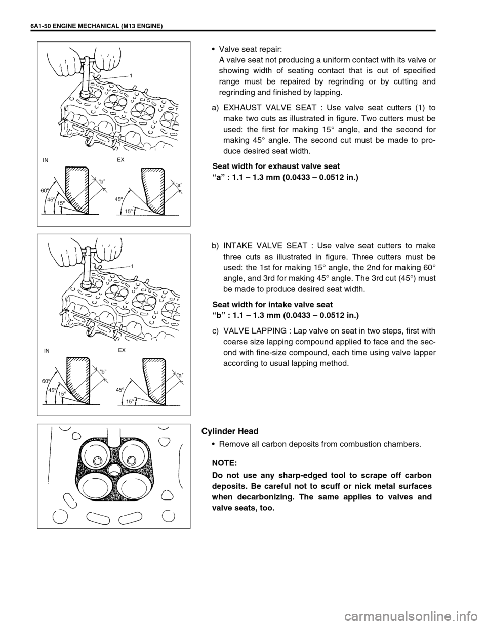
Valve seat repair:
A valve seat not producing a uniform contact with its valve or
showing width of seating contact that is out of specified
range must be repaired by regrinding or by cutting and
regrinding and finished by lapping.
a) EXHAUST VALVE SEAT : Use valve seat cutters (1) to
make two cuts as illustrated in figure. Two cutters must be
used: the first for making 15° angle, and the second for
making 45° angle. The second cut must be made to pro-
duce desired seat width.
Seat width for exhaust valve seat
“a” : 1.1 – 1.3 mm (0.0433 – 0.0512 in.)
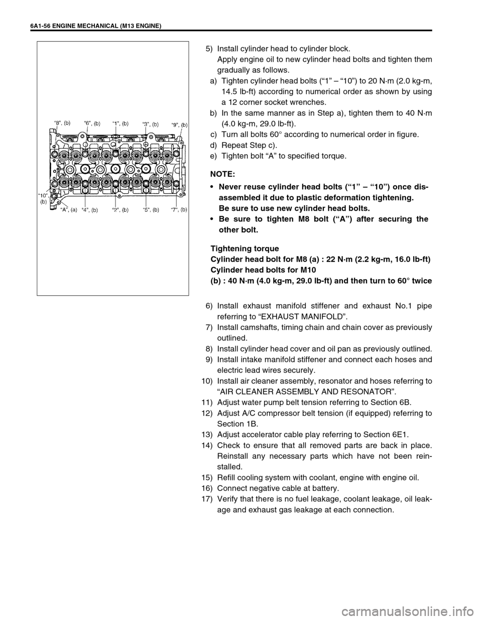
b) INTAKE VALVE SEAT : Use valve seat cutters to make
three cuts as illustrated in figure. Three cutters must be
used: the 1st for making 15° angle, the 2nd for making 60°
angle, and 3rd for making 45° angle. The 3rd cut (45°) must
be made to produce desired seat width.
Seat width for intake valve seat
“b” : 1.1 – 1.3 mm (0.0433 – 0.0512 in.)
c) VALVE LAPPING : Lap valve on seat in two steps, first with
coarse size lapping compound applied to face and the sec-
ond with fine-size compound, each time using valve lapper
according to usual lapping method.
Cylinder Head
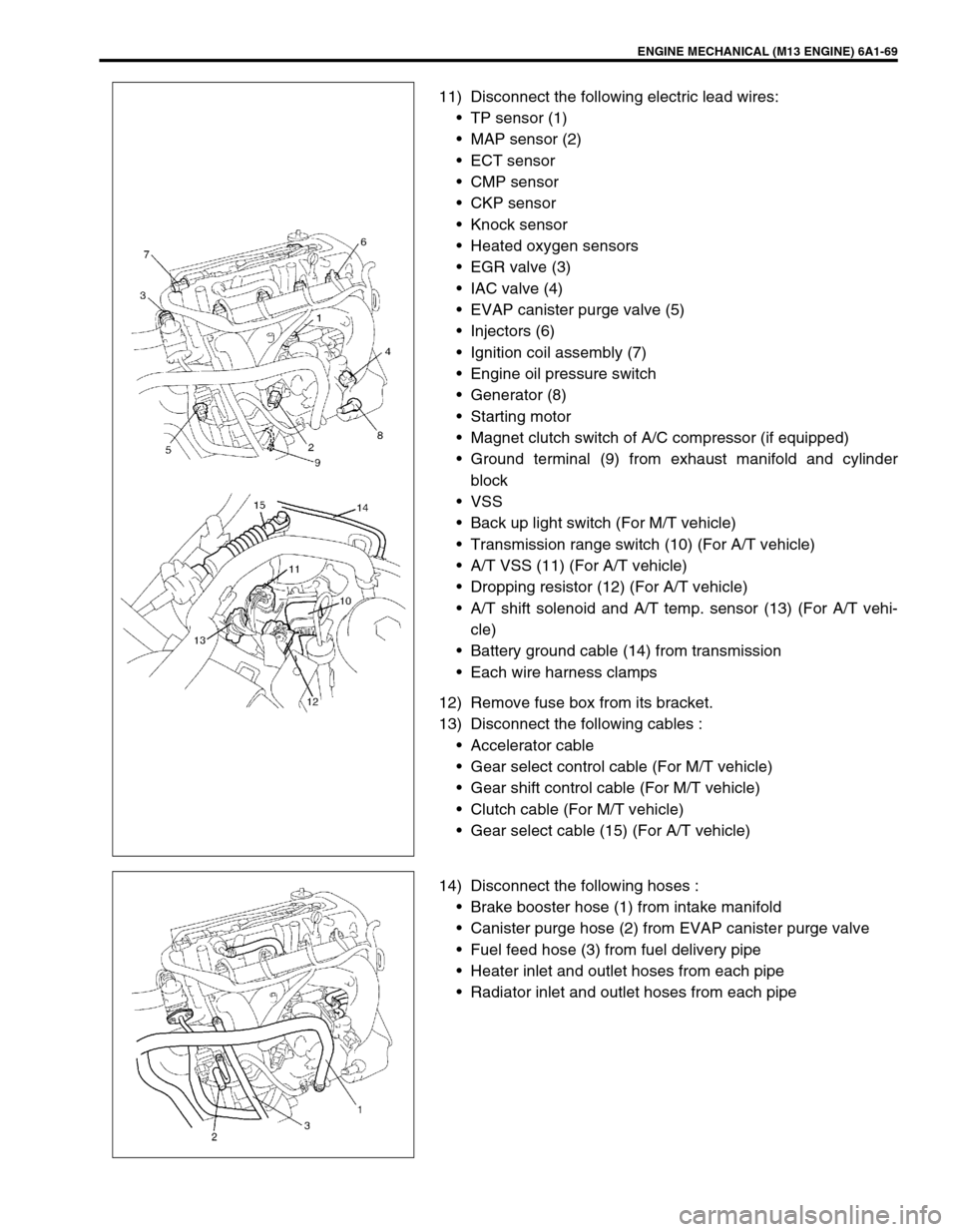
Remove all carbon deposits from combustion chambers.
NOTE:
Do not use any sharp-edged tool to scrape off carbon
deposits. Be careful not to scuff or nick metal surfaces
when decarbonizing. The same applies to valves and
valve seats, too.
Page 552 of 698

ENGINE MECHANICAL (M13 ENGINE) 6A1-51
Check cylinder head for cracks on intake and exhaust ports,
combustion chambers, and head surface.
Using a straightedge and thickness gauge, check flatness of
gasketed surface at a total of 2 locations. If distortion limit,
given below, is exceeded, correct gasketed surface with a
surface plate and abrasive paper of about #400 (Waterproof
silicon carbide abrasive paper): place abrasive paper on and
over surface plate, and rub gasketed surface against paper
to grind off high spots. Should this fail to reduce thickness
gauge readings to within limit, replace cylinder head.
Leakage of combustion gases from this gasketed joint is
often due to warped gasketed surface: such leakage results
in reduced power output.
Limit of distortion for cylinder head surface on piston side
: 0.03 mm (0.001 in.)
Distortion of manifold seating faces:
Check seating faces of cylinder head for manifolds, using a
straightedge and thickness gauge, in order to determine
whether these faces should be corrected or cylinder head
replaced.
Limit of distortion for cylinder head surface on intake and
exhaust manifold
: 0.05 mm (0.002 in.)
Page 554 of 698

ENGINE MECHANICAL (M13 ENGINE) 6A1-53
ASSEMBLY
1) Before installing valve guide into cylinder head, ream guide
hole with special tool (11 mm reamer for engine equipped
with 69G type valve or 10.5 mm reamer for engine equipped
with 54G type valve) so as to remove burrs and make it truly
round.
Special tool
(A) : 09916-34542
(B) : 09916-38210 (11 mm) for engine equipped with 69G
type valve
(B) : 09916-37320 (10.5 mm) for engine equipped with 54G
type valve
2) Install valve guide to cylinder head.
Heat cylinder head uniformly to a temperature of 80 to 100
°C (176 to 212 °F) so that head will not be distorted, and
drive new valve guide into hole with special tools. Drive in
new valve guide until special tool (Valve guide installer) con-
tacts cylinder head.
After installing, make sure that valve guide protrudes by
specified dimension “a” from cylinder head.
Special tool
(A) : 09916-57350 (For engine equipped with 69G type
valve)
(A) : 09916-58210 (For engine equipped with 54G type
valve)
(B) : 09917-88240 (For Intake side of engine equipped with
69G type valve)
(B) : 09917-88250 (For Exhaust side of engine equipped
with 69G type valve)
(B) : 09916-56011 (For both sides of engine equipped with
54G type valve)
Specification for valve guide protrusion “a”
Intake side of engine equipped with 69G type valve
: 17.5 mm (0.71 in.)
Exhaust side of engine equipped with 69G type valve
: 14.5 mm (0.57 in.)
Both sides of engine equipped with 54G type valve
: 11.1 – 11.5 mm (0.44 – 0.45 in.)
1. Valve
2. Emboss mark 54G or 69G
NOTE:
Never reuse once-disassembled valve guide.
Make sure to install new valve guide.
Intake and exhaust valve guides are identical.
1. Valve
2. Emboss mark 54G or 69G
Page 556 of 698

ENGINE MECHANICAL (M13 ENGINE) 6A1-55
7) Install valve spring and spring retainer.
Each valve spring has top end (large-pitch end (1)) and bot-
tom end (small-pitch end (2)). Be sure to position spring in
place with its bottom end (small-pitch end) facing the bottom
(valve spring seat side).
8) Using special tools (Valve lifter), compress valve spring and
fit two valve cotters (1) into groove in valve stem.
Special tool
(A) : 09916-14510
(B) : 09916-14910
(C) : 09916-84511
9) Install intake manifold, injectors and exhaust manifold to cyl-
inder head.
INSTALLATION
1) Clean mating surface of cylinder head and cylinder block.
Remove oil, old gasket and dust from mating surface.
2) Install knock pins (1) to cylinder block.
3) Install new cylinder head gasket (2) to cylinder block.
“TOP” mark provided on gasket comes to crankshaft pulley
side, facing up (toward cylinder head side).
4) Make sure that oil jet (venturi plug) (1) is installed and if it is,
that it is not clogged.
When installing it, be sure to tighten to specified torque.
Tightening torque
Venturi plug (a) : 5 N·m (0.5 kg-m, 3.5 lb-ft)
A : Valve spring retainer side
B : Valve spring seat side
NOTE:
When compressing the valve spring, be carefully to free
from damage in inside face of tappet installing hole.
Page 557 of 698

6A1-56 ENGINE MECHANICAL (M13 ENGINE)
5) Install cylinder head to cylinder block.
Apply engine oil to new cylinder head bolts and tighten them
gradually as follows.
a) Tighten cylinder head bolts (“1” – “10”) to 20 N·m (2.0 kg-m,
14.5 lb-ft) according to numerical order as shown by using
a 12 corner socket wrenches.
b) In the same manner as in Step a), tighten them to 40 N·m
(4.0 kg-m, 29.0 lb-ft).
c) Turn all bolts 60° according to numerical order in figure.
d) Repeat Step c).
e) Tighten bolt “A” to specified torque.
Tightening torque
Cylinder head bolt for M8 (a) : 22 N·m (2.2 kg-m, 16.0 lb-ft)
Cylinder head bolts for M10
(b) : 40 N·m (4.0 kg-m, 29.0 lb-ft) and then turn to 60° twice
6) Install exhaust manifold stiffener and exhaust No.1 pipe
referring to “EXHAUST MANIFOLD”.
7) Install camshafts, timing chain and chain cover as previously
outlined.
8) Install cylinder head cover and oil pan as previously outlined.
9) Install intake manifold stiffener and connect each hoses and
electric lead wires securely.
10) Install air cleaner assembly, resonator and hoses referring to
“AIR CLEANER ASSEMBLY AND RESONATOR”.
11) Adjust water pump belt tension referring to Section 6B.
12) Adjust A/C compressor belt tension (if equipped) referring to
Section 1B.
13) Adjust accelerator cable play referring to Section 6E1.
14) Check to ensure that all removed parts are back in place.
Reinstall any necessary parts which have not been rein-
stalled.
15) Refill cooling system with coolant, engine with engine oil.
16) Connect negative cable at battery.
17) Verify that there is no fuel leakage, coolant leakage, oil leak-
age and exhaust gas leakage at each connection. NOTE:
Never reuse cylinder head bolts (“1” – “10”) once dis-
assembled it due to plastic deformation tightening.
Be sure to use new cylinder head bolts.
Be sure to tighten M8 bolt (“A”) after securing the
other bolt.
Page 567 of 698
6A1-66 ENGINE MECHANICAL (M13 ENGINE)
6) Reverse removal procedure for installation as previously out-
lined.
7) Adjust water pump belt tension referring to Section 6B.
8) Adjust A/C compressor belt tension (if equipped) referring to
Section 1B.
9) Adjust accelerator cable play referring to Section 6E1.
10) Check to ensure that all removed parts are back in place.
Reinstall any necessary parts which have not been rein-
stalled.
11) Refill cooling system with coolant engine with engine oil.
12) Connect negative cable at battery.
13) Verify that there is no fuel leakage, coolant leakage, oil leak-
age and exhaust gas leakage at each connection. NOTE:
Before installing bearing cap, make sure that checking
for connecting rod bolt deformation.
Refer to “INSPECTION” of “CONNECTING ROD”.
Page 570 of 698

ENGINE MECHANICAL (M13 ENGINE) 6A1-69
11) Disconnect the following electric lead wires:
TP sensor (1)
MAP sensor (2)
ECT sensor
CMP sensor
CKP sensor
Knock sensor
Heated oxygen sensors
EGR valve (3)
IAC valve (4)
EVAP canister purge valve (5)
Injectors (6)
Ignition coil assembly (7)
Engine oil pressure switch
Generator (8)
Starting motor
Magnet clutch switch of A/C compressor (if equipped)
Ground terminal (9) from exhaust manifold and cylinder
block
VSS
Back up light switch (For M/T vehicle)
Transmission range switch (10) (For A/T vehicle)
A/T VSS (11) (For A/T vehicle)
Dropping resistor (12) (For A/T vehicle)
A/T shift solenoid and A/T temp. sensor (13) (For A/T vehi-
cle)
Battery ground cable (14) from transmission
Each wire harness clamps
12) Remove fuse box from its bracket.
13) Disconnect the following cables :
Accelerator cable
Gear select control cable (For M/T vehicle)
Gear shift control cable (For M/T vehicle)
Clutch cable (For M/T vehicle)
Gear select cable (15) (For A/T vehicle)
14) Disconnect the following hoses :
Brake booster hose (1) from intake manifold
Canister purge hose (2) from EVAP canister purge valve
Fuel feed hose (3) from fuel delivery pipe
Heater inlet and outlet hoses from each pipe
Radiator inlet and outlet hoses from each pipe
Page 571 of 698
6A1-70 ENGINE MECHANICAL (M13 ENGINE)
15) Remove exhaust No.1 pipe (1).
16) Disconnect right and left drive shaft joints from differential
gear referring to Section 4.
For engine and transmission removal, it is not necessary to
remove drive shafts from steering knuckle.
17) For 4WD vehicle, remove propeller shaft referring to Section
4B.
18) Remove generator referring to Section 6H.
19) Install lifting device.
20) Remove engine rear mounting bolts (1), engine left mounting
bracket nuts (2) and engine right mounting bolts (3).