Page 644 of 698

ENGINE AND EMISSION CONTROL SYSTEM 6E1-23
2) Turn OFF ignition switch and leave over 10 minutes as it is.
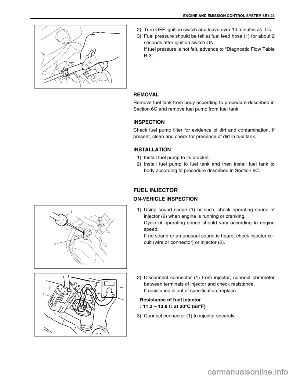
3) Fuel pressure should be felt at fuel feed hose (1) for about 2
seconds after ignition switch ON.
If fuel pressure is not felt, advance to “Diagnostic Flow Table
B-3”.
REMOVAL
Remove fuel tank from body according to procedure described in
Section 6C and remove fuel pump from fuel tank.
INSPECTION
Check fuel pump filter for evidence of dirt and contamination. If
present, clean and check for presence of dirt in fuel tank.
INSTALLATION
1) Install fuel pump to its bracket.
2) Install fuel pump to fuel tank and then install fuel tank to
body according to procedure described in Section 6C.
FUEL INJECTOR
ON-VEHICLE INSPECTION
1) Using sound scope (1) or such, check operating sound of
injector (2) when engine is running or cranking.
Cycle of operating sound should vary according to engine
speed.
If no sound or an unusual sound is heard, check injector cir-
cuit (wire or connector) or injector (2).
2) Disconnect connector (1) from injector, connect ohmmeter
between terminals of injector and check resistance.
If resistance is out of specification, replace.
Resistance of fuel injector
: 11.3 – 13.8
Ω at 20°C (68°F)
3) Connect connector (1) to injector securely.
Page 646 of 698

ENGINE AND EMISSION CONTROL SYSTEM 6E1-25
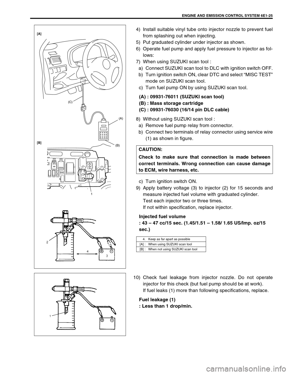
4) Install suitable vinyl tube onto injector nozzle to prevent fuel
from splashing out when injecting.
5) Put graduated cylinder under injector as shown.
6) Operate fuel pump and apply fuel pressure to injector as fol-
lows:
7) When using SUZUKI scan tool :
a) Connect SUZUKI scan tool to DLC with ignition switch OFF.
b) Turn ignition switch ON, clear DTC and select “MISC TEST”
mode on SUZUKI scan tool.
c) Turn fuel pump ON by using SUZUKI scan tool.
(A) : 09931-76011 (SUZUKI scan tool)
(B) : Mass storage cartridge
(C) : 09931-76030 (16/14 pin DLC cable)
8) Without using SUZUKI scan tool :
a) Remove fuel pump relay from connector.
b) Connect two terminals of relay connector using service wire
(1) as shown in figure.
c) Turn ignition switch ON.
9) Apply battery voltage (3) to injector (2) for 15 seconds and
measure injected fuel volume with graduated cylinder.
Test each injector two or three times.
If not within specification, replace injector.
Injected fuel volume
: 43 – 47 cc/15 sec. (1.45/1.51 – 1.58/ 1.65 US/Imp. oz/15
sec.)
10) Check fuel leakage from injector nozzle. Do not operate
injector for this check (but fuel pump should be at work).
If fuel leaks (1) more than following specifications, replace.
Fuel leakage (1)
: Less than 1 drop/min. CAUTION:
Check to make sure that connection is made between
correct terminals. Wrong connection can cause damage
to ECM, wire harness, etc.
4. Keep as far apart as possible
[A] : When using SUZUKI scan tool
[B] : When not using SUZUKI scan tool
(C)
(A)
(B)
1 [A]
[B]
Page 654 of 698

ENGINE AND EMISSION CONTROL SYSTEM 6E1-33
VEHICLE SPEED SENSOR (VSS)
INSPECTION
Check vehicle speed sensor referring to step 3 of DTC P0500
(No.16) Flow Table. If malfunction is found, replace.
REMOVAL/INSTALLATION
Refer to Section 7A.
FUEL LEVEL SENSOR (GAUGE)
INSPECTION
Refer to Section 8.
REMOVAL/INSTALLATION
Refer to Section 6C.
KNOCK SENSOR (IF EQUIPPED)
INSPECTION
Check knock sensor referring to DTC P0325 (No.17) Flow Table.
If malfunction is found, replace.
REMOVAL/INSTALLATION
Refer to Section 6A.
MAIN RELAY, FUEL PUMP RELAY AND RADIATOR
FAN RELAY NO.1
INSPECTION
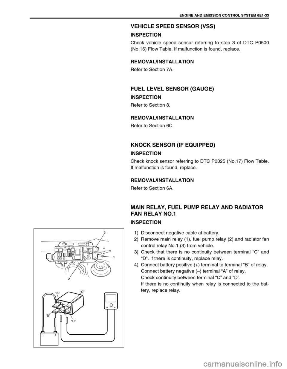
1) Disconnect negative cable at battery.
2) Remove main relay (1), fuel pump relay (2) and radiator fan
control relay No.1 (3) from vehicle.
3) Check that there is no continuity between terminal “C” and
“D”. If there is continuity, replace relay.
4) Connect battery positive (+) terminal to terminal “B” of relay.
Connect battery negative (–) terminal “A” of relay.
Check continuity between terminal “C” and “D”.
If there is no continuity when relay is connected to the bat-
tery, replace relay.
“D” “B”“A”“C”
3
1
2