2000 SUZUKI SWIFT Electric system
[x] Cancel search: Electric systemPage 557 of 698
6A1-56 ENGINE MECHANICAL (M13 ENGINE)
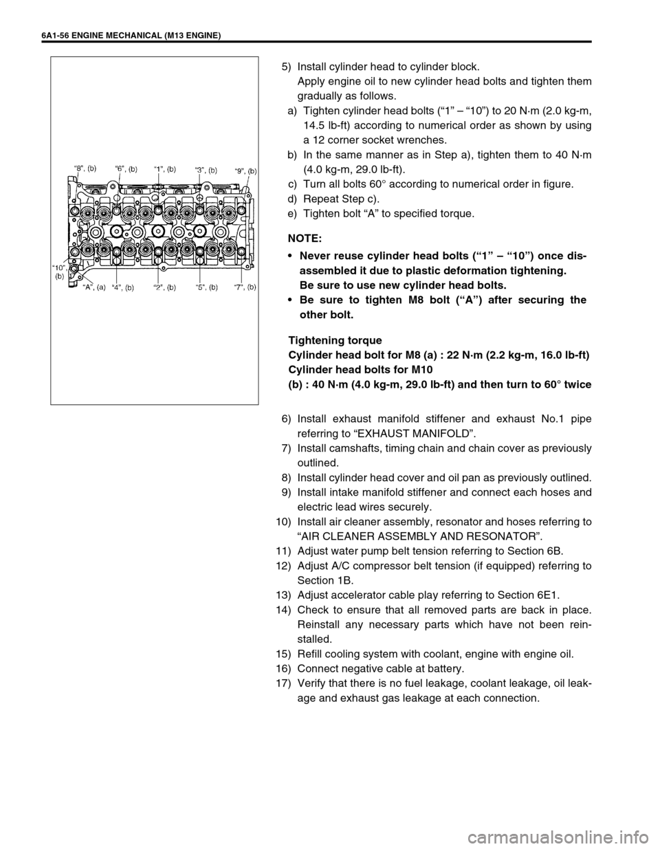
5) Install cylinder head to cylinder block.
Apply engine oil to new cylinder head bolts and tighten them
gradually as follows.
a) Tighten cylinder head bolts (“1” – “10”) to 20 N·m (2.0 kg-m,
14.5 lb-ft) according to numerical order as shown by using
a 12 corner socket wrenches.
b) In the same manner as in Step a), tighten them to 40 N·m
(4.0 kg-m, 29.0 lb-ft).
c) Turn all bolts 60° according to numerical order in figure.
d) Repeat Step c).
e) Tighten bolt “A” to specified torque.
Tightening torque
Cylinder head bolt for M8 (a) : 22 N·m (2.2 kg-m, 16.0 lb-ft)
Cylinder head bolts for M10
(b) : 40 N·m (4.0 kg-m, 29.0 lb-ft) and then turn to 60° twice
6) Install exhaust manifold stiffener and exhaust No.1 pipe
referring to “EXHAUST MANIFOLD”.
7) Install camshafts, timing chain and chain cover as previously
outlined.
8) Install cylinder head cover and oil pan as previously outlined.
9) Install intake manifold stiffener and connect each hoses and
electric lead wires securely.
10) Install air cleaner assembly, resonator and hoses referring to
“AIR CLEANER ASSEMBLY AND RESONATOR”.
11) Adjust water pump belt tension referring to Section 6B.
12) Adjust A/C compressor belt tension (if equipped) referring to
Section 1B.
13) Adjust accelerator cable play referring to Section 6E1.
14) Check to ensure that all removed parts are back in place.
Reinstall any necessary parts which have not been rein-
stalled.
15) Refill cooling system with coolant, engine with engine oil.
16) Connect negative cable at battery.
17) Verify that there is no fuel leakage, coolant leakage, oil leak-
age and exhaust gas leakage at each connection. NOTE:
Never reuse cylinder head bolts (“1” – “10”) once dis-
assembled it due to plastic deformation tightening.
Be sure to use new cylinder head bolts.
Be sure to tighten M8 bolt (“A”) after securing the
other bolt.
Page 573 of 698
6A1-72 ENGINE MECHANICAL (M13 ENGINE)
6) Install generator referring to Section 6H.
7) For 4WD vehicle, install propeller shaft referring to Section
4B.
8) Connect drive shaft joints referring to Section 4.
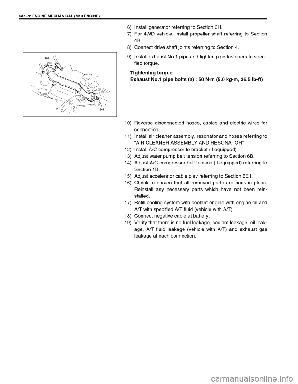
9) Install exhaust No.1 pipe and tighten pipe fasteners to speci-
fied torque.
Tightening torque
Exhaust No.1 pipe bolts (a) : 50 N·m (5.0 kg-m, 36.5 lb-ft)
10) Reverse disconnected hoses, cables and electric wires for
connection.
11) Install air cleaner assembly, resonator and hoses referring to
“AIR CLEANER ASSEMBLY AND RESONATOR”
12) Install A/C compressor to bracket (if equipped).
13) Adjust water pump belt tension referring to Section 6B.
14) Adjust A/C compressor belt tension (if equipped) referring to
Section 1B.
15) Adjust accelerator cable play referring to Section 6E1.
16) Check to ensure that all removed parts are back in place.
Reinstall any necessary parts which have not been rein-
stalled.
17) Refill cooling system with coolant engine with engine oil and
A/T with specified A/T fluid (vehicle with A/T).
18) Connect negative cable at battery.
19) Verify that there is no fuel leakage, coolant leakage, oil leak-
age, A/T fluid leakage (vehicle with A/T) and exhaust gas
leakage at each connection.
Page 593 of 698
6B-4 ENGINE COOLING
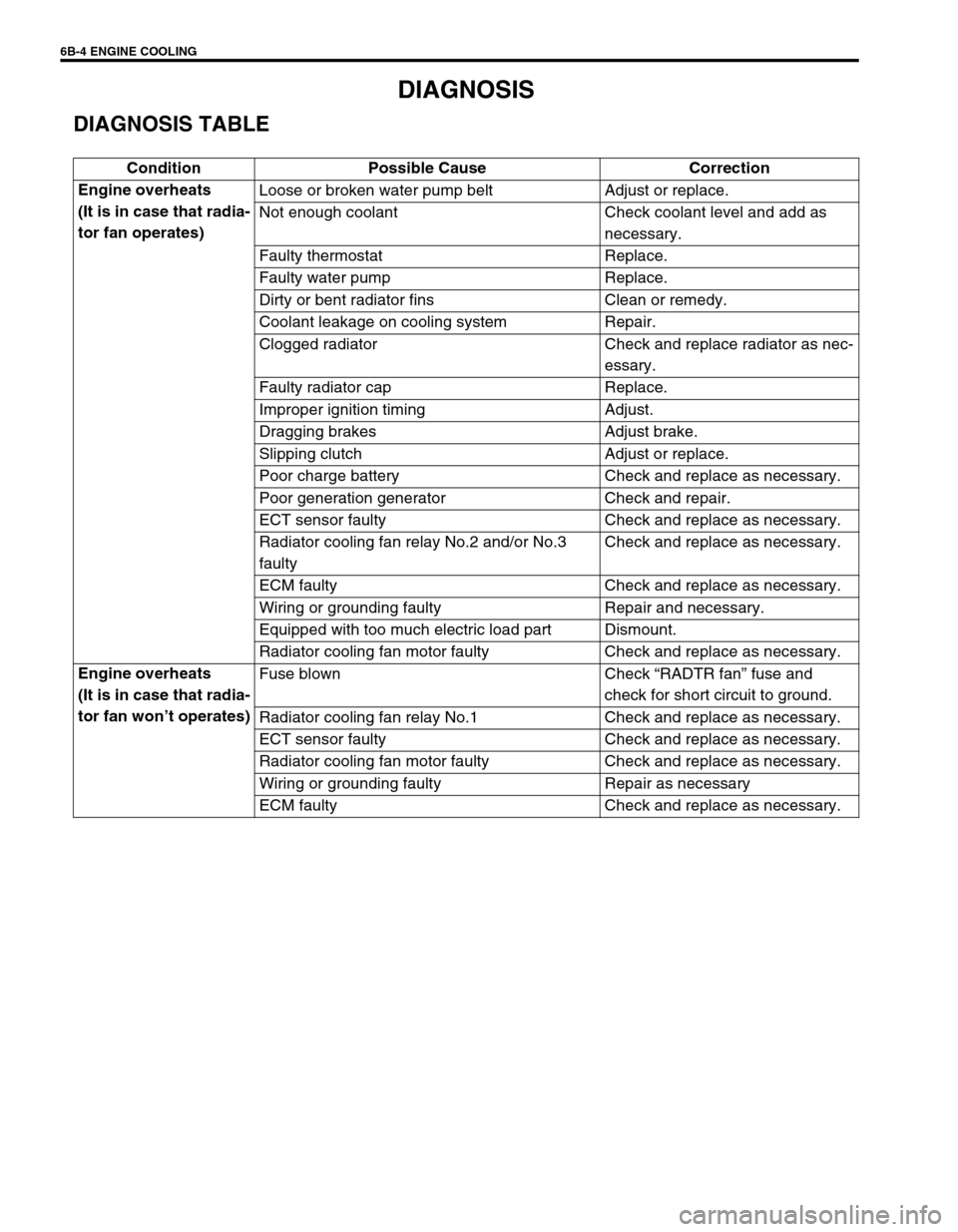
DIAGNOSIS
DIAGNOSIS TABLE
Condition Possible Cause Correction
Engine overheats
(It is in case that radia-
tor fan operates)Loose or broken water pump belt Adjust or replace.
Not enough coolant Check coolant level and add as
necessary.
Faulty thermostat Replace.
Faulty water pump Replace.
Dirty or bent radiator fins Clean or remedy.
Coolant leakage on cooling system Repair.
Clogged radiator Check and replace radiator as nec-
essary.
Faulty radiator cap Replace.
Improper ignition timing Adjust.
Dragging brakes Adjust brake.
Slipping clutch Adjust or replace.
Poor charge battery Check and replace as necessary.
Poor generation generator Check and repair.
ECT sensor faulty Check and replace as necessary.
Radiator cooling fan relay No.2 and/or No.3
faultyCheck and replace as necessary.
ECM faulty Check and replace as necessary.
Wiring or grounding faulty Repair and necessary.
Equipped with too much electric load part Dismount.
Radiator cooling fan motor faulty Check and replace as necessary.
Engine overheats
(It is in case that radia-
tor fan won’t operates)Fuse blown Check “RADTR fan” fuse and
check for short circuit to ground.
Radiator cooling fan relay No.1 Check and replace as necessary.
ECT sensor faulty Check and replace as necessary.
Radiator cooling fan motor faulty Check and replace as necessary.
Wiring or grounding faulty Repair as necessary
ECM faulty Check and replace as necessary.
Page 626 of 698
ENGINE AND EMISSION CONTROL SYSTEM 6E1-5
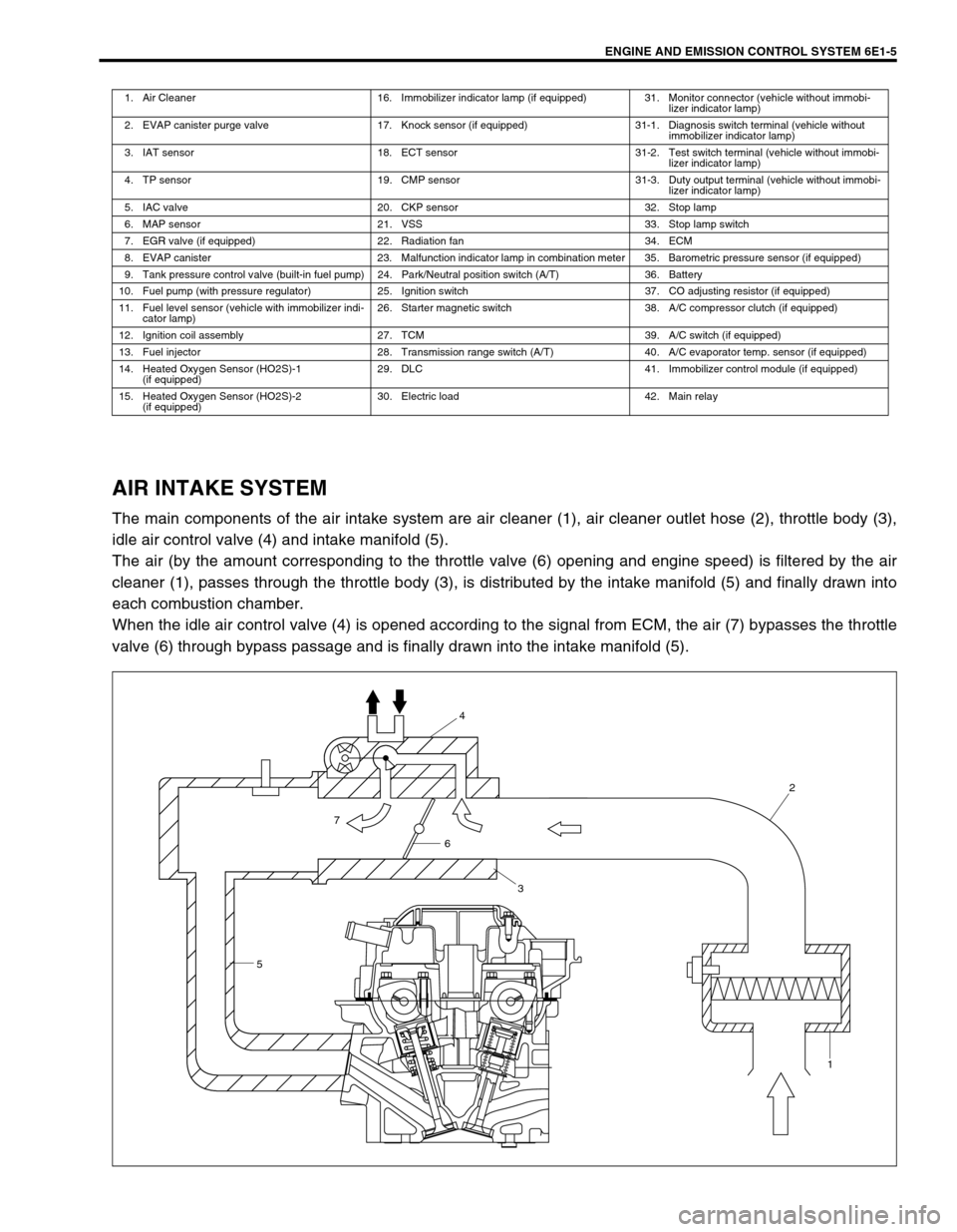
AIR INTAKE SYSTEM
The main components of the air intake system are air cleaner (1), air cleaner outlet hose (2), throttle body (3),
idle air control valve (4) and intake manifold (5).
The air (by the amount corresponding to the throttle valve (6) opening and engine speed) is filtered by the air
cleaner (1), passes through the throttle body (3), is distributed by the intake manifold (5) and finally drawn into
each combustion chamber.
When the idle air control valve (4) is opened according to the signal from ECM, the air (7) bypasses the throttle
valve (6) through bypass passage and is finally drawn into the intake manifold (5).
1. Air Cleaner 16. Immobilizer indicator lamp (if equipped) 31. Monitor connector (vehicle without immobi-
lizer indicator lamp)
2. EVAP canister purge valve 17. Knock sensor (if equipped) 31-1. Diagnosis switch terminal (vehicle without
immobilizer indicator lamp)
3. IAT sensor 18. ECT sensor 31-2. Test switch terminal (vehicle without immobi-
lizer indicator lamp)
4. TP sensor 19. CMP sensor 31-3. Duty output terminal (vehicle without immobi-
lizer indicator lamp)
5. IAC valve 20. CKP sensor 32. Stop lamp
6. MAP sensor 21. VSS 33. Stop lamp switch
7. EGR valve (if equipped) 22. Radiation fan 34. ECM
8. EVAP canister 23. Malfunction indicator lamp in combination meter 35. Barometric pressure sensor (if equipped)
9. Tank pressure control valve (built-in fuel pump) 24. Park/Neutral position switch (A/T) 36. Battery
10. Fuel pump (with pressure regulator) 25. Ignition switch 37. CO adjusting resistor (if equipped)
11. Fuel level sensor (vehicle with immobilizer indi-
cator lamp)26. Starter magnetic switch 38. A/C compressor clutch (if equipped)
12. Ignition coil assembly 27. TCM 39. A/C switch (if equipped)
13. Fuel injector 28. Transmission range switch (A/T) 40. A/C evaporator temp. sensor (if equipped)
14. Heated Oxygen Sensor (HO2S)-1
(if equipped)29. DLC 41. Immobilizer control module (if equipped)
15. Heated Oxygen Sensor (HO2S)-2
(if equipped)30. Electric load 42. Main relay
54
2
1
6
3
7
Page 627 of 698

6E1-6 ENGINE AND EMISSION CONTROL SYSTEM
FUEL DELIVERY SYSTEM
The fuel system consists of fuel tank (1), fuel pump (2) (with built-in fuel filter (3) and fuel pressure regulator (4)),
delivery pipe (5), injectors (6) and fuel feed line (7).
The fuel (8) in the fuel tank (1) is pumped up by the fuel pump (2), sent into delivery pipe (5) and injected by the
injectors (6).
As the fuel pump assembly is equipped with built-in fuel filter (3) and fuel pressure regulator (4), the fuel (8) is fil-
tered and its pressure is regulated before being sent to the delivery pipe (5).
The excess fuel from fuel pressure regulation process is returned back (9) into the fuel tank.
Also, fuel vapor generated in fuel tank is led through the fuel vapor line (10) into the EVAP canister (12).
FUEL PUMP
An in-tank type electric pump has been adopted for the fuel pump
(1). Incorporated in the pump assembly are;
Tank pressure control valve (2) which keeps the pressure in
the fuel tank constant, and prevents the fuel from spouting
and tank itself from being deformed.
Relief valve (3) which prevents the pressure in tank from ris-
ing excessively.
Fuel cut valve (4) which closes as the float rises so that the
fuel will not enter the canister when the fuel level in the tank
rises high depending on the fuel level in the tank and the
vehicle tilt angle.
Also, a fuel filter (5) and a fuel pressure regulator (6) are included
and a fuel level gauge (7) is attached.
Addition of the fuel pressure regulator (6) to the fuel pump makes
it possible to maintain the fuel pressure at constant level and
ECM controls compensation for variation in the intake manifold
pressure.
11. Intake manifold
Page 629 of 698
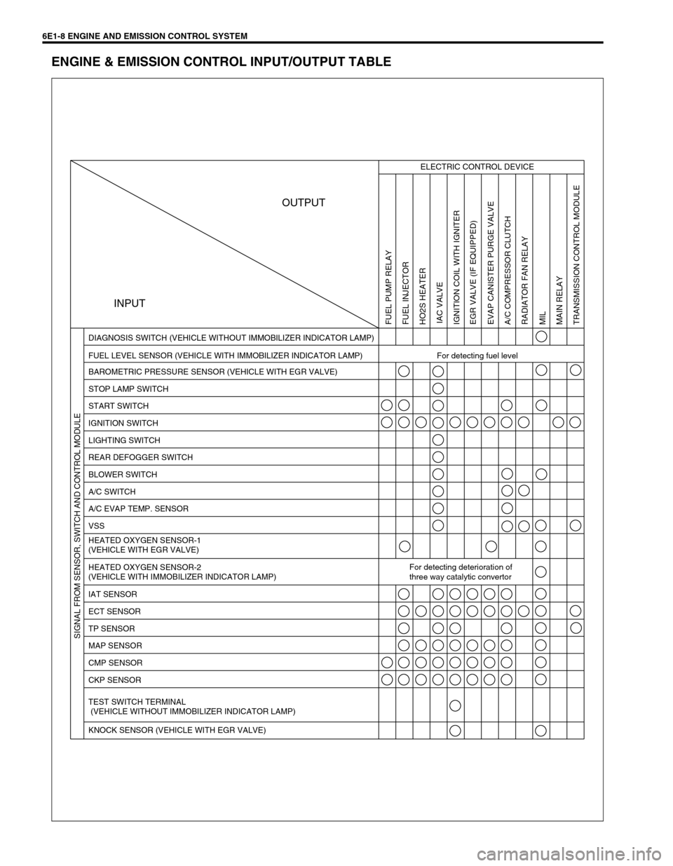
6E1-8 ENGINE AND EMISSION CONTROL SYSTEM
ENGINE & EMISSION CONTROL INPUT/OUTPUT TABLE
INPUTOUTPUT
ELECTRIC CONTROL DEVICE
FUEL LEVEL SENSOR (VEHICLE WITH IMMOBILIZER INDICATOR LAMP) For detecting fuel level DIAGNOSIS SWITCH (VEHICLE WITHOUT IMMOBILIZER INDICATOR LAMP)
BAROMETRIC PRESSURE SENSOR (VEHICLE WITH EGR VALVE)
STOP LAMP SWITCH
START SWITCH
IGNITION SWITCH
LIGHTING SWITCH
REAR DEFOGGER SWITCH
BLOWER SWITCH
A/C SWITCH
A/C EVAP TEMP. SENSOR
VSS
HEATED OXYGEN SENSOR-1
(VEHICLE WITH EGR VALVE)
HEATED OXYGEN SENSOR-2
(VEHICLE WITH IMMOBILIZER INDICATOR LAMP)For detecting deterioration of
three way catalytic convertor
IAT SENSOR
ECT SENSOR
TP SENSOR
MAP SENSOR
CMP SENSOR
CKP SENSOR
TEST SWITCH TERMINAL
(VEHICLE WITHOUT IMMOBILIZER INDICATOR LAMP)
KNOCK SENSOR (VEHICLE WITH EGR VALVE)
FUEL PUMP RELAY
FUEL INJECTOR
HO2S HEATER
IAC VALVE
IGNITION COIL WITH IGNITER
EGR VALVE (IF EQUIPPED)
EVAP CANISTER PURGE VALVE
A/C COMPRESSOR CLUTCH
RADIATOR FAN RELAY
MIL
MAIN RELAY
TRANSMISSION CONTROL MODULE SIGNAL FROM SENSOR, SWITCH AND CONTROL MODULE
Page 634 of 698

ENGINE AND EMISSION CONTROL SYSTEM 6E1-13
ECM TERMINAL ARRANGEMENT TABLE
For TYPE A (Refer to NOTE in page “ECM INPUT/OUTPUT CIRCUIT DIAGRAM” for applicable model.)
CONNEC-
TORTERMINAL WIRE COLOR CIRCUITCONNEC-
TORTERMINAL WIRE COLOR CIRCUIT
C421 BLK/ORN Ground for ECM
C4112––
2 BLK Ground for drive circuit 13–Heated oxygen sensor-2
3 BLK/ORN Ground for drive circuit 14 LT BLU“D”, “2”, “L”-range ID-UP signal
4 BLU/BLK Canister purge valve 15 RED“R”-range signal
5 WHT/BLK Coolant temp. signal output 16 YEL/GRN A/C SW signal
6 GRN/RED IAC valve 17 BRN/YEL EGR valve (stepper motor coil 4)
7 RED/BLU Heater of HO2S-1 18 BLU Radiator fan relay 1
8 BLU/ORN No.4 fuel injector 19 PNK Fuel pump relay
9 BLU/YEL No.1 fuel injector 20––
10 ORN Ground for sensor circuit 21 PPL Throttle opening signal output for A/T
11 RED/YEL CMP sensor 22 YEL/RED Fuel level gauge
12 RED Knock sensor (if equipped) 23 BLK/WHT TCM serial data line
13 WHTHeated oxygen sensor-1
(if equipped)
24––
CO adjusting resistor
(if equipped)
14 LT GRN Coolant temp. sensor
15 LT GRN/BLK Intake air temp. sensor
G021 PPL/WHT Malfunction indicator lamp
16 WHT/GRN Test switch terminal (if equipped) 2 PPL Vehicle speed sensor
17 RED/BLK Electric load (+) 3 PPL/YEL Radiator fan relay 2
18 PNK/GRN A/C switch 4––
19 GRN/WHTIG coil assembly for No.2 and 3 spark
plugs5 BLU Data link connector
20 GRN/YELIG coil assembly for No.1 and 4 spark
plugs6 BLK/WHT Ignition switch signal
21 BLU/WHT No.2 fuel injector 7 YEL Data link connector
22 GRY/RED Power supply for sensor 8––
23 YEL/BLK CKP sensor (+) 9 GRN/WHTStop lamp switch (Brake pedal
switch)
24––10 ORN GND for sensor
25–Ground for sensor shield wire 11––
26 RED/WHT MAP sensor 12 PNKImmobilizer indicator lamp
(if equipped)
27 PPL/WHTDiagnosis switch terminal
(if equipped)13 PNK/BLU Electrical load (-)
28 PNK/BLU Duty output terminal (if equipped) 14 WHT/BLK A/C evaporator temp. sensor
29 BRN Heater of HO2S-2 15––
30 GRN/BLK Heated oxygen sensor-2 16 BRN Tachometer signal
31 BLU/RED No.3 fuel injector 17 WHT/RED Backup power source
C411 PNK/BLK A/C compressor clutch
2 GRN EGR valve (stepper motor coil 1)
3 GRY/BLU Throttle position (TP) sensor
4–Heater of HO2S-2
5 BLK/RED Power source
6 BLK/RED Power source
7 BLK/YEL Engine start signal
8 WHT/RED EGR valve (stepper motor coil 3)
9 GRN/ORN EGR valve (stepper motor coil 2)
10 BRN/WHT Ground for main relay
11––
C42 (31P) C41 (24P) G02 (17P)1 2 3 4 5 6 7 8 9
10 11 12 13 14 15 16 17 18 19 20 21
22 23 24 25 26 28 27 29 30 315 6
1 2 3 4 5 6 7
11 12
9 10 11 13 12 14 15 16
16 171 2
7 8
13 14 3 4
9 10
15 17 188
19 20 21 22 23 24
NOTE:
For abbreviation of wire color, refer to Section 0A.
Page 635 of 698

6E1-14 ENGINE AND EMISSION CONTROL SYSTEM
For TYPE B (Refer to NOTE in page “ECM INPUT/OUTPUT CIRCUIT DIAGRAM” for applicable model.)
CONNEC-
TORTERMINAL WIRE COLOR CIRCUITCONNEC-
TORTERMINAL WIRE COLOR CIRCUIT
C421 BLK/ORN Ground for ECM
C4112––
2 BLK Ground for drive circuit 13––
3 BLK/ORN Ground for drive circuit 14 PPL/WHT Diagnosis switch terminal
4 BLU/BLK Canister purge valve 15 WHT/GRN Test switch terminal
5––16 YEL/GRN A/C SW signal
6 GRN/RED IAC valve 17 RED/YEL
Electric load (+)
7 RED/BLU Heater of HO2S-1 18 BLU Radiator fan relay 1
8 BLU/ORN No.4 fuel injector 19 PNK Fuel pump relay
9 BLU/YEL No.1 fuel injector 20 BLK/YEL
Cranking signal
10 ORN Ground for sensor circuit 21 GRN/WHTStop lamp switch (Brake pedal
switch)
11 RED/YEL CMP sensor 22 PPL Vehicle speed sensor
12 Or Grand for shield wire 23––
13 WHTHeated oxygen sensor-1
(if equipped)
24––
CO adjusting resistor
(if equipped)
14 LT GRN Coolant temp. sensor
15 LT GRN/BLK Intake air temp. sensor
G021 WHT/BLK A/C evaporator temp. sensor
16 GRY/BLU Throttle position (TP) sensor 2 RED“R” range signal
17 WHT/RED EGR valve (stepper motor coil 3) 3––
18 GRY EGR valve (stepper motor coil 1) 4––
19 GRN/WHTIG coil assembly for No.2 and 3 spark
plugs5 WHT/BLK Engine coolant temp. signals output
20 GRN/YELIG coil assembly for No.1 and 4 spark
plugs6 GRN/RED“D”, “2”, “L” range ID-UP signal
21 BLU/WHT No.2 fuel injector 7 YEL Data link connector
22 GRY/RED Power supply for sensor 8––
23 YEL/BLK CKP sensor (+) 9 PPL/WHT Malfunction indicator lamp
24––10––
25 RED Knock sensor (if equipped) 11 BLU
Data link connector
26 RED/WHT MAP sensor 12––
27––13 PNK/BLU Electrical load (-)
28 BRN/YEL EGR valve (stepper motor coil 4) 14 ORN Ground for sensor
29 GRN/ORNEGR valve (stepper motor coil 2)
15 PPL
Throttle opening signal output for
A/T
30 PNK/GRN A/C switch 16 BRN Tachometer signal
31 BLU/RED No.3 fuel injector 17––
C411 PNK/BLK A/C compressor clutch
2––
3––
4––
5 BLK/RED Power source for drive circuit
6 BLK/RED Power source for main circuit
7 WHT/RED Power source for memory circuit
8 PNK/BLU Duty signal output terminal
9 GRN/RED Radiator fan drive relay No.2
10 BRN/WHT Ground for main relay
11 BLK/WHT
Ignition switch signal
C42 (31P) C41 (24P) G02 (17P)1 2 3 4 5 6 7 8 9
10 11 12 13 14 15 16 17 18 19 20 21
22 23 24 25 26 28 27 29 30 315 6
1 2 3 4 5 6 7
11 12
9 10 11 13 12 14 15 16
16 171 2
7 8
13 14 3 4
9 10
15 17 188
19 20 21 22 23 24
NOTE:
For abbreviation of wire color, refer to Section 0A.