Page 567 of 698
6A1-66 ENGINE MECHANICAL (M13 ENGINE)
6) Reverse removal procedure for installation as previously out-
lined.
7) Adjust water pump belt tension referring to Section 6B.
8) Adjust A/C compressor belt tension (if equipped) referring to
Section 1B.
9) Adjust accelerator cable play referring to Section 6E1.
10) Check to ensure that all removed parts are back in place.
Reinstall any necessary parts which have not been rein-
stalled.
11) Refill cooling system with coolant engine with engine oil.
12) Connect negative cable at battery.
13) Verify that there is no fuel leakage, coolant leakage, oil leak-
age and exhaust gas leakage at each connection. NOTE:
Before installing bearing cap, make sure that checking
for connecting rod bolt deformation.
Refer to “INSPECTION” of “CONNECTING ROD”.
Page 569 of 698
6A1-68 ENGINE MECHANICAL (M13 ENGINE)
UNIT REPAIR OVERHAUL
ENGINE ASSEMBLY
REMOVAL
1) Relieve fuel pressure according to procedure described in
Section 6.
2) Disconnect negative and positive cables at battery.
3) Remove engine hood after disconnecting windshield washer
hose.
4) Remove right and left side engine under covers.
5) Remove A/C compressor belt (if equipped).
6) Remove water pump belt.
7) Drain engine oil, transmission oil or A/T fluid (for A/T vehicle)
and transfer oil (for 4WD vehicle).
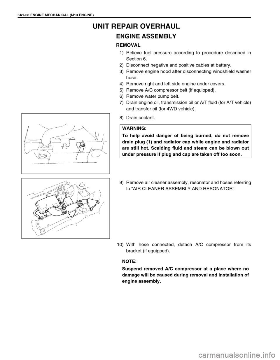
8) Drain coolant.
9) Remove air cleaner assembly, resonator and hoses referring
to “AIR CLEANER ASSEMBLY AND RESONATOR”.
10) With hose connected, detach A/C compressor from its
bracket (if equipped). WARNING:
To help avoid danger of being burned, do not remove
drain plug (1) and radiator cap while engine and radiator
are still hot. Scalding fluid and steam can be blown out
under pressure if plug and cap are taken off too soon.
NOTE:
Suspend removed A/C compressor at a place where no
damage will be caused during removal and installation of
engine assembly.
Page 573 of 698
6A1-72 ENGINE MECHANICAL (M13 ENGINE)
6) Install generator referring to Section 6H.
7) For 4WD vehicle, install propeller shaft referring to Section
4B.
8) Connect drive shaft joints referring to Section 4.
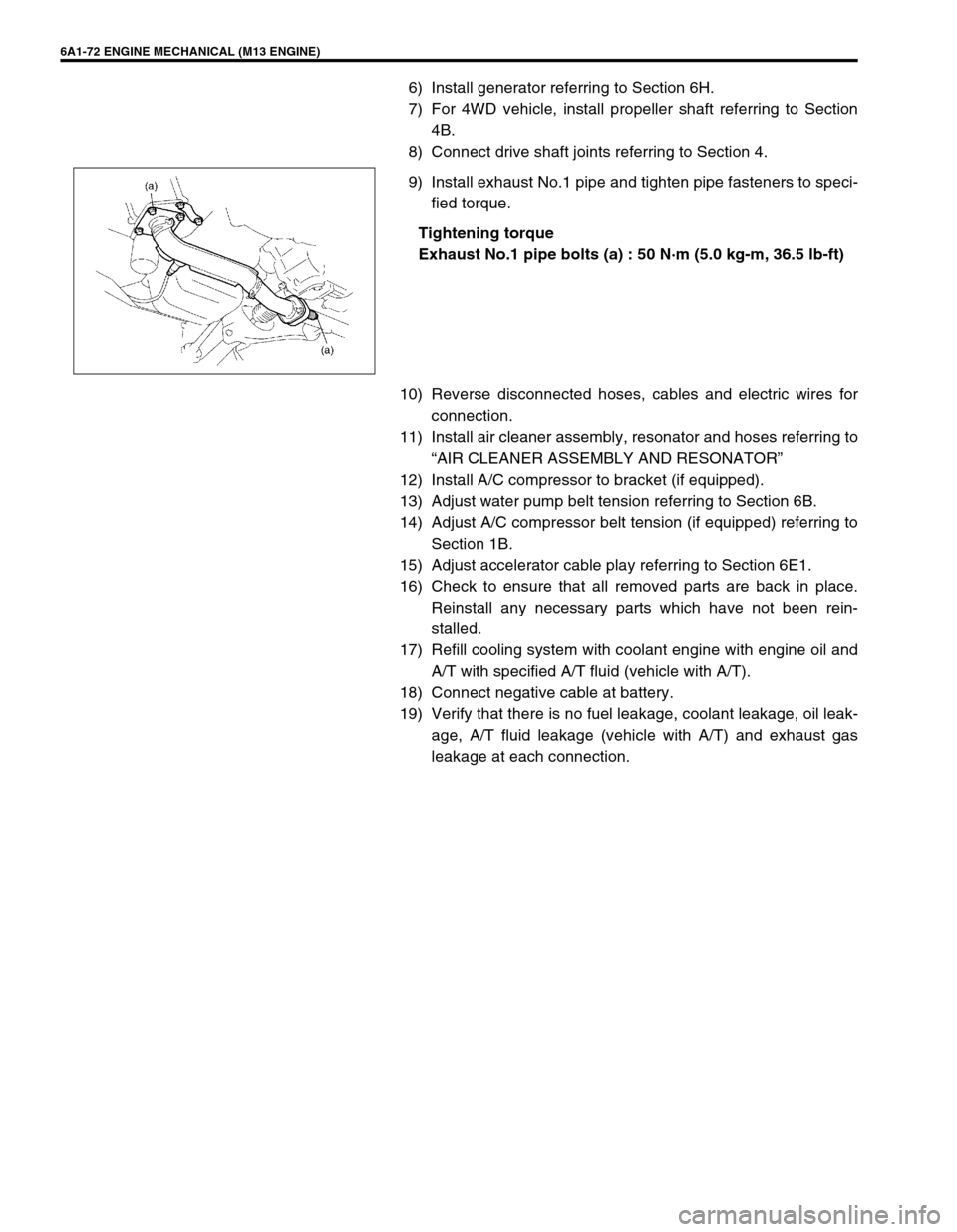
9) Install exhaust No.1 pipe and tighten pipe fasteners to speci-
fied torque.
Tightening torque
Exhaust No.1 pipe bolts (a) : 50 N·m (5.0 kg-m, 36.5 lb-ft)
10) Reverse disconnected hoses, cables and electric wires for
connection.
11) Install air cleaner assembly, resonator and hoses referring to
“AIR CLEANER ASSEMBLY AND RESONATOR”
12) Install A/C compressor to bracket (if equipped).
13) Adjust water pump belt tension referring to Section 6B.
14) Adjust A/C compressor belt tension (if equipped) referring to
Section 1B.
15) Adjust accelerator cable play referring to Section 6E1.
16) Check to ensure that all removed parts are back in place.
Reinstall any necessary parts which have not been rein-
stalled.
17) Refill cooling system with coolant engine with engine oil and
A/T with specified A/T fluid (vehicle with A/T).
18) Connect negative cable at battery.
19) Verify that there is no fuel leakage, coolant leakage, oil leak-
age, A/T fluid leakage (vehicle with A/T) and exhaust gas
leakage at each connection.
Page 590 of 698
ENGINE COOLING 6B-1
6B
SECTION 6B
ENGINE COOLING
CONTENTS
GENERAL DESCRIPTION ...............................6B-2
COOLING SYSTEM CIRCULATION............. 6B-2
COOLANT ..................................................... 6B-3
DIAGNOSIS ......................................................6B-4
DIAGNOSIS TABLE ...................................... 6B-4
SYSTEM CIRCUIT ........................................ 6B-5
SYSTEM CIRCUIT INSPECTION ................. 6B-5
MAINTENANCE................................................6B-6
COOLANT LEVEL CHECK ........................... 6B-6
ENGINE COOLING SYSTEM
INSPECTION AND SERVICE ....................... 6B-7
COOLING SYSTEM FLUSH AND REFILL ... 6B-7
WATER PUMP/GENERATOR DRIVE
BELT TENSION INSPECTION AND
ADJUSTMENT .............................................. 6B-9
ON-VEHICLE SERVICE .................................6B-10SYSTEM COMPONENTS .......................... 6B-10
COOLING SYSTEM DRAINING ................. 6B-11
COOLING SYSTEM REFILL ...................... 6B-11
COOLING WATER PIPES OR HOSES ...... 6B-12
THERMOSTAT ........................................... 6B-12
RADIATOR ................................................. 6B-14
RADIATOR AND CONDENSER
COOLING FAN ........................................... 6B-15
RADIATOR AND CONDENSER
COOLING FAN RELAY .............................. 6B-15
WATER PUMP/GENERATOR
DRIVE BELT ............................................... 6B-15
WATER PUMP............................................ 6B-16
ECT SENSOR............................................. 6B-18
REQUIRED SERVICE MATERIAL................. 6B-18
TIGHTENING TORQUE SPECIFICATION..... 6B-18
Page 591 of 698
6B-2 ENGINE COOLING
GENERAL DESCRIPTION
The cooling system consists of the radiator cap, radiator, coolant reservoir tank, hoses, water pump, cooling fan
and thermostat. The radiator is of tube-and-fin type.
COOLING SYSTEM CIRCULATION
While the engine is warmed up (thermostat closed), coolant circulates as follows.
When coolant is warmed up to normal temperature and the thermostat opens, coolant passes through the radi-
ator core to be cooled as well as the above flow circuit.
1. Radiator inlet hose 5. Water pump 9. Heater outlet hose
2. Radiator outlet hose 6. Throttle body (Fast idle control plunger) 10. Radiator
3. Water inlet pipe 7. Engine
4. Thermostat 8. Heater inlet hose
Water pump Cylinder block
Thermostat closedCylinder head Water intake pipeThrottle body
Heater unit
Page 592 of 698
ENGINE COOLING 6B-3
COOLANT
The coolant recovery system is standard. The coolant in the radiator expands with heat, and the overflow is col-
lected in the reservoir.
When the system cools down, the coolant is drawn back into the radiator.
The cooling system has been filled at the factory with a quality coolant that is a 50/50 mixture of water and eth-
ylene glycol antifreeze (70/30; in a market where no freezing temperature is anticipated).
This 50/50 mixture coolant solution provides freezing protection to –36°C (–33°F).
Maintain cooling system freeze protection at –36°C (–33°F) to ensure protection against corrosion and loss
of coolant from boiling. This should be done even if freezing temperatures are not expected.
Add ethylene glycol base coolant when coolant has to be added because of coolant loss or to provide added
protection against freezing at temperature lower than –36°C (–33°F).
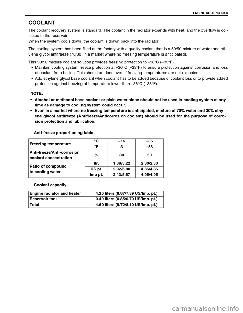
Anti-freeze proportioning table
Coolant capacity NOTE:
Alcohol or methanol base coolant or plain water alone should not be used in cooling system at any
time as damage to cooling system could occur.
Even in a market where no freezing temperature is anticipated, mixture of 70% water and 30% ethyl-
ene glycol antifreeze (Antifreeze/Anticorrosion coolant) should be used for the purpose of corro-
sion protection and lubrication.
Freezing temperature°C–16–36
°F3–33
Anti-freeze/Anti-corrosion
coolant concentration%30 50
Ratio of compound
to cooling waterItr. 1.38/3.22 2.30/2.30
US pt. 2.92/6.80 4.86/4.86
Imp pt. 2.43/5.67 4.05/4.05
Engine radiator and heater 4.20 liters (8.87/7.39 US/lmp. pt.)
Reservoir tank 0.40 liters (0.85/0.70 US/lmp. pt.)
Total 4.60 liters (9.72/8.10 US/lmp. pt.)
Page 593 of 698
6B-4 ENGINE COOLING
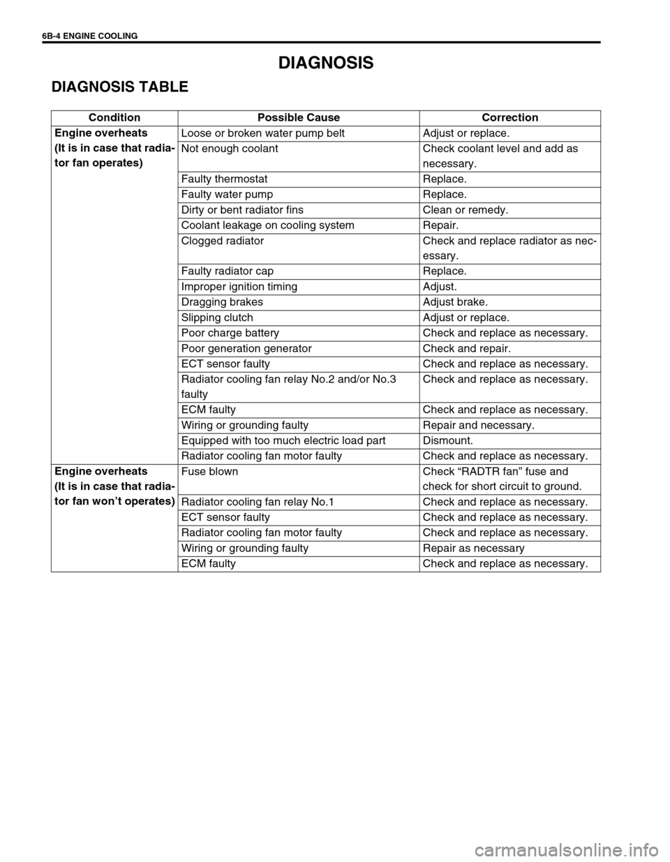
DIAGNOSIS
DIAGNOSIS TABLE
Condition Possible Cause Correction
Engine overheats
(It is in case that radia-
tor fan operates)Loose or broken water pump belt Adjust or replace.
Not enough coolant Check coolant level and add as
necessary.
Faulty thermostat Replace.
Faulty water pump Replace.
Dirty or bent radiator fins Clean or remedy.
Coolant leakage on cooling system Repair.
Clogged radiator Check and replace radiator as nec-
essary.
Faulty radiator cap Replace.
Improper ignition timing Adjust.
Dragging brakes Adjust brake.
Slipping clutch Adjust or replace.
Poor charge battery Check and replace as necessary.
Poor generation generator Check and repair.
ECT sensor faulty Check and replace as necessary.
Radiator cooling fan relay No.2 and/or No.3
faultyCheck and replace as necessary.
ECM faulty Check and replace as necessary.
Wiring or grounding faulty Repair and necessary.
Equipped with too much electric load part Dismount.
Radiator cooling fan motor faulty Check and replace as necessary.
Engine overheats
(It is in case that radia-
tor fan won’t operates)Fuse blown Check “RADTR fan” fuse and
check for short circuit to ground.
Radiator cooling fan relay No.1 Check and replace as necessary.
ECT sensor faulty Check and replace as necessary.
Radiator cooling fan motor faulty Check and replace as necessary.
Wiring or grounding faulty Repair as necessary
ECM faulty Check and replace as necessary.
Page 595 of 698
6B-6 ENGINE COOLING
MAINTENANCE
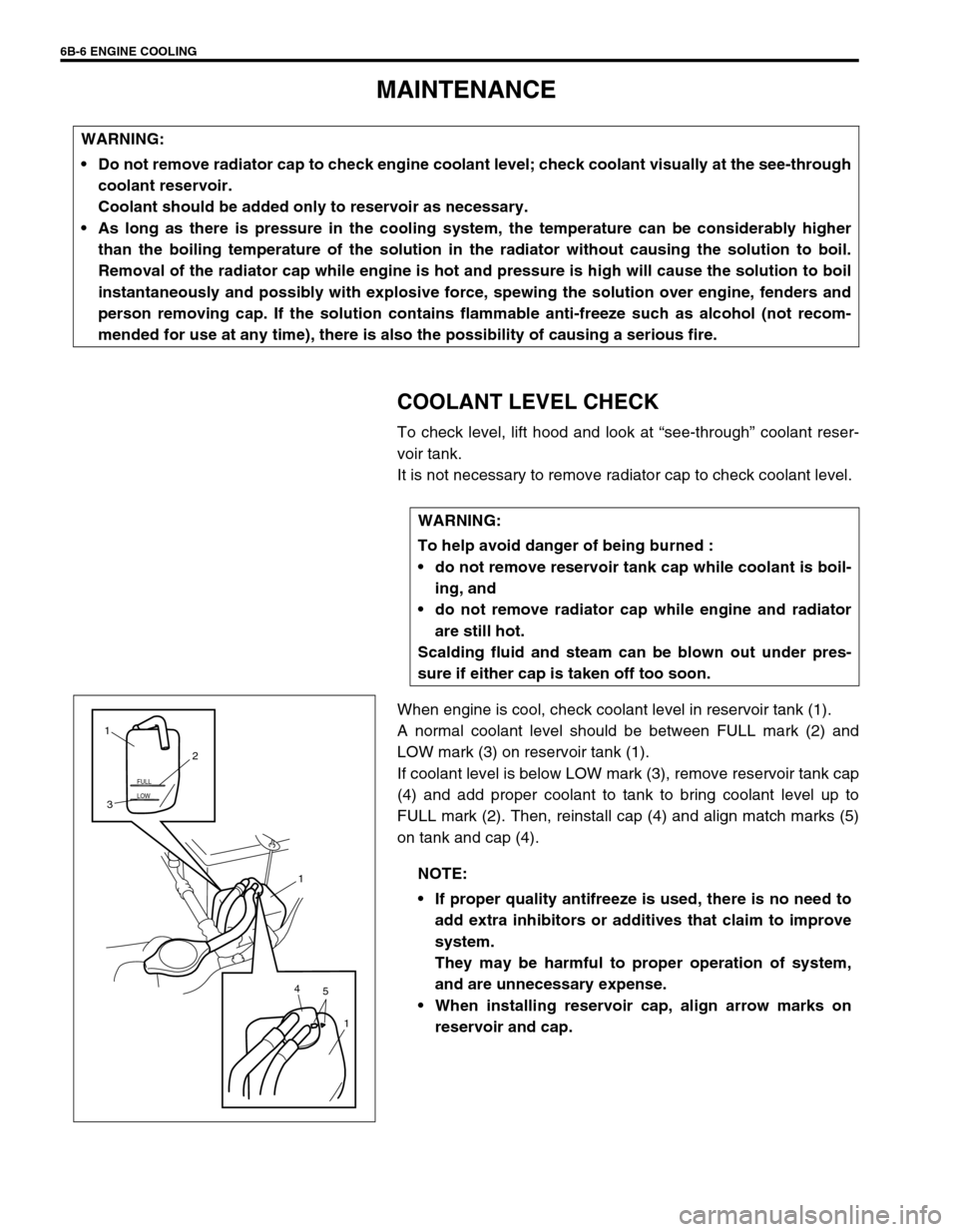
COOLANT LEVEL CHECK
To check level, lift hood and look at “see-through” coolant reser-
voir tank.
It is not necessary to remove radiator cap to check coolant level.
When engine is cool, check coolant level in reservoir tank (1).
A normal coolant level should be between FULL mark (2) and
LOW mark (3) on reservoir tank (1).
If coolant level is below LOW mark (3), remove reservoir tank cap
(4) and add proper coolant to tank to bring coolant level up to
FULL mark (2). Then, reinstall cap (4) and align match marks (5)
on tank and cap (4). WARNING:
Do not remove radiator cap to check engine coolant level; check coolant visually at the see-through
coolant reservoir.
Coolant should be added only to reservoir as necessary.
As long as there is pressure in the cooling system, the temperature can be considerably higher
than the boiling temperature of the solution in the radiator without causing the solution to boil.
Removal of the radiator cap while engine is hot and pressure is high will cause the solution to boil
instantaneously and possibly with explosive force, spewing the solution over engine, fenders and
person removing cap. If the solution contains flammable anti-freeze such as alcohol (not recom-
mended for use at any time), there is also the possibility of causing a serious fire.
WARNING:
To help avoid danger of being burned :
do not remove reservoir tank cap while coolant is boil-
ing, and
do not remove radiator cap while engine and radiator
are still hot.
Scalding fluid and steam can be blown out under pres-
sure if either cap is taken off too soon.
NOTE:
If proper quality antifreeze is used, there is no need to
add extra inhibitors or additives that claim to improve
system.
They may be harmful to proper operation of system,
and are unnecessary expense.
When installing reservoir cap, align arrow marks on
reservoir and cap.
LOW FULL
5 41
1 32 1