Page 545 of 698
6A1-44 ENGINE MECHANICAL (M13 ENGINE)
VALVES AND CYLINDER HEAD
REMOVAL
1) Relieve fuel pressure according to procedure described in
Section 6.
2) Disconnect negative cable at battery.
3) Drain engine oil.
[A]✱1) Tighten all bolts at 40 N·m (4.0 kg-m)
2) Turn all bolts at 60°
3) Then, Turn all bolt at 60° once again6. Intake valve 12. Knock pin
1. Valve cotters 7. Exhaust valve
Tightening torque
2. Valve spring retainer 8. Valve guide
Do not reuse.
3. Valve spring 9. Cylinder head bolt
: Never reuse it due to plastic deformation
tightening bolt.Apply engine oil to sliding surface of
each part.
4. Valve stem seal 10. Cylinder head
5. Valve spring seat 11. Cylinder head gasket
: “TOP” mark provided on gasket comes to
crankshaft pulley side, facing up.
Page 546 of 698
ENGINE MECHANICAL (M13 ENGINE) 6A1-45
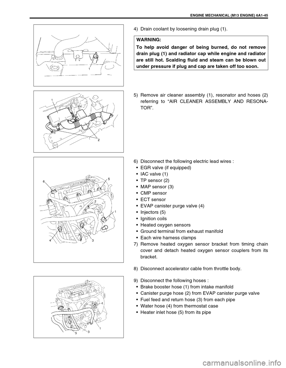
4) Drain coolant by loosening drain plug (1).
5) Remove air cleaner assembly (1), resonator and hoses (2)
referring to “AIR CLEANER ASSEMBLY AND RESONA-
TOR”.
6) Disconnect the following electric lead wires :
EGR valve (if equipped)
IAC valve (1)
TP sensor (2)
MAP sensor (3)
CMP sensor
ECT sensor
EVAP canister purge valve (4)
Injectors (5)
Ignition coils
Heated oxygen sensors
Ground terminal from exhaust manifold
Each wire harness clamps
7) Remove heated oxygen sensor bracket from timing chain
cover and detach heated oxygen sensor couplers from its
bracket.
8) Disconnect accelerator cable from throttle body.
9) Disconnect the following hoses :
Brake booster hose (1) from intake manifold
Canister purge hose (2) from EVAP canister purge valve
Fuel feed and return hose (3) from each pipe
Water hose (4) from thermostat case
Heater inlet hose (5) from its pipe WARNING:
To help avoid danger of being burned, do not remove
drain plug (1) and radiator cap while engine and radiator
are still hot. Scalding fluid and steam can be blown out
under pressure if plug and cap are taken off too soon.
Page 558 of 698
ENGINE MECHANICAL (M13 ENGINE) 6A1-57
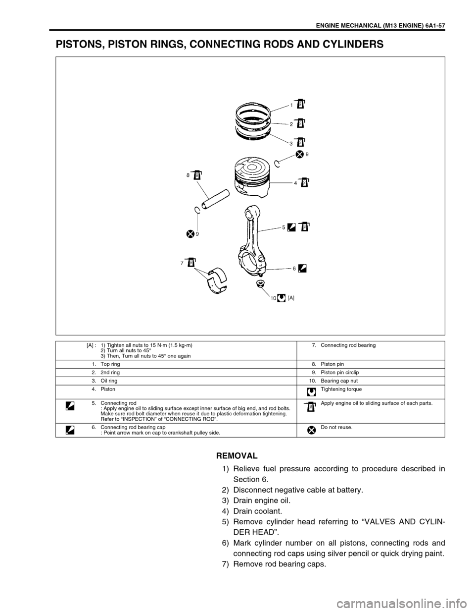
PISTONS, PISTON RINGS, CONNECTING RODS AND CYLINDERS
REMOVAL
1) Relieve fuel pressure according to procedure described in
Section 6.
2) Disconnect negative cable at battery.
3) Drain engine oil.
4) Drain coolant.
5) Remove cylinder head referring to “VALVES AND CYLIN-
DER HEAD”.
6) Mark cylinder number on all pistons, connecting rods and
connecting rod caps using silver pencil or quick drying paint.
7) Remove rod bearing caps.
[A] : 1) Tighten all nuts to 15 N·m (1.5 kg-m)
2) Turn all nuts to 45°
3) Then, Turn all nuts to 45° one again7. Connecting rod bearing
1. Top ring8. Piston pin
2. 2nd ring9. Piston pin circlip
3. Oil ring10. Bearing cap nut
4. PistonTightening torque
5. Connecting rod
: Apply engine oil to sliding surface except inner surface of big end, and rod bolts.
Make sure rod bolt diameter when reuse it due to plastic deformation tightening.
Refer to “INSPECTION” of “CONNECTING ROD”.Apply engine oil to sliding surface of each parts.
6. Connecting rod bearing cap
: Point arrow mark on cap to crankshaft pulley side.Do not reuse.
Page 569 of 698
6A1-68 ENGINE MECHANICAL (M13 ENGINE)
UNIT REPAIR OVERHAUL
ENGINE ASSEMBLY
REMOVAL
1) Relieve fuel pressure according to procedure described in
Section 6.
2) Disconnect negative and positive cables at battery.
3) Remove engine hood after disconnecting windshield washer
hose.
4) Remove right and left side engine under covers.
5) Remove A/C compressor belt (if equipped).
6) Remove water pump belt.
7) Drain engine oil, transmission oil or A/T fluid (for A/T vehicle)
and transfer oil (for 4WD vehicle).
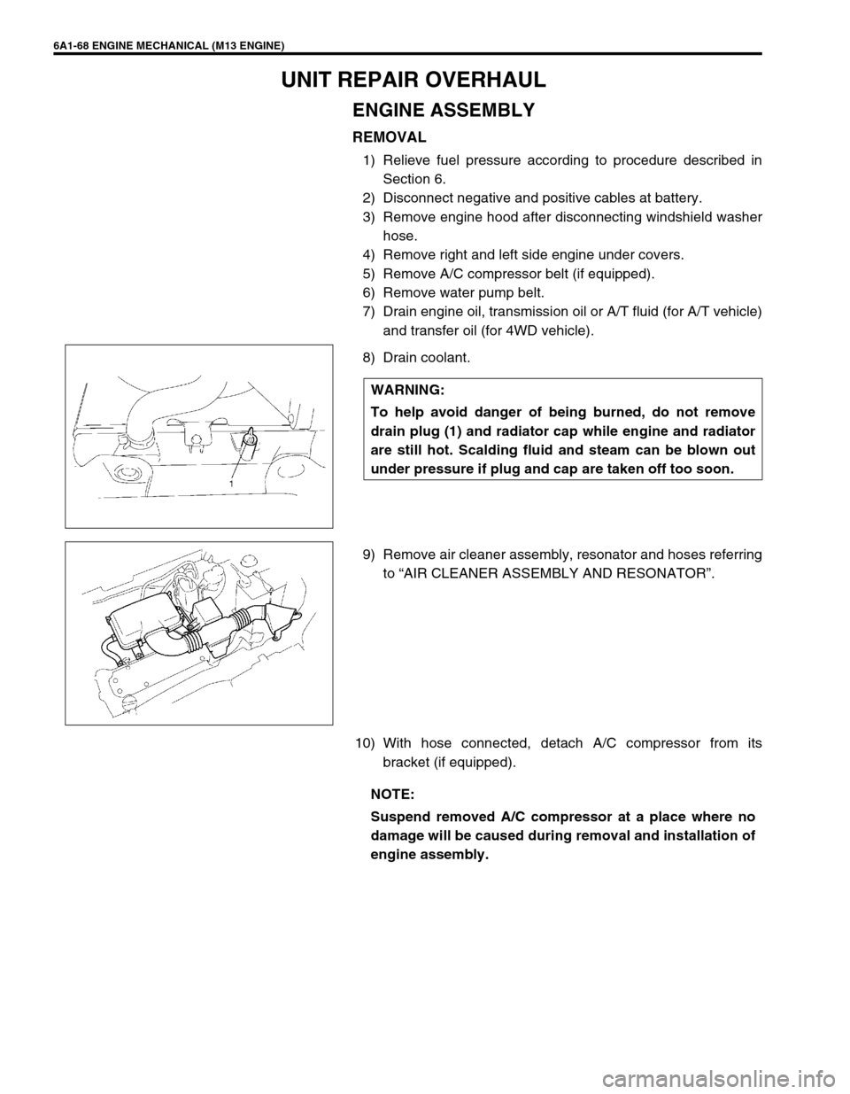
8) Drain coolant.
9) Remove air cleaner assembly, resonator and hoses referring
to “AIR CLEANER ASSEMBLY AND RESONATOR”.
10) With hose connected, detach A/C compressor from its
bracket (if equipped). WARNING:
To help avoid danger of being burned, do not remove
drain plug (1) and radiator cap while engine and radiator
are still hot. Scalding fluid and steam can be blown out
under pressure if plug and cap are taken off too soon.
NOTE:
Suspend removed A/C compressor at a place where no
damage will be caused during removal and installation of
engine assembly.
Page 570 of 698
ENGINE MECHANICAL (M13 ENGINE) 6A1-69
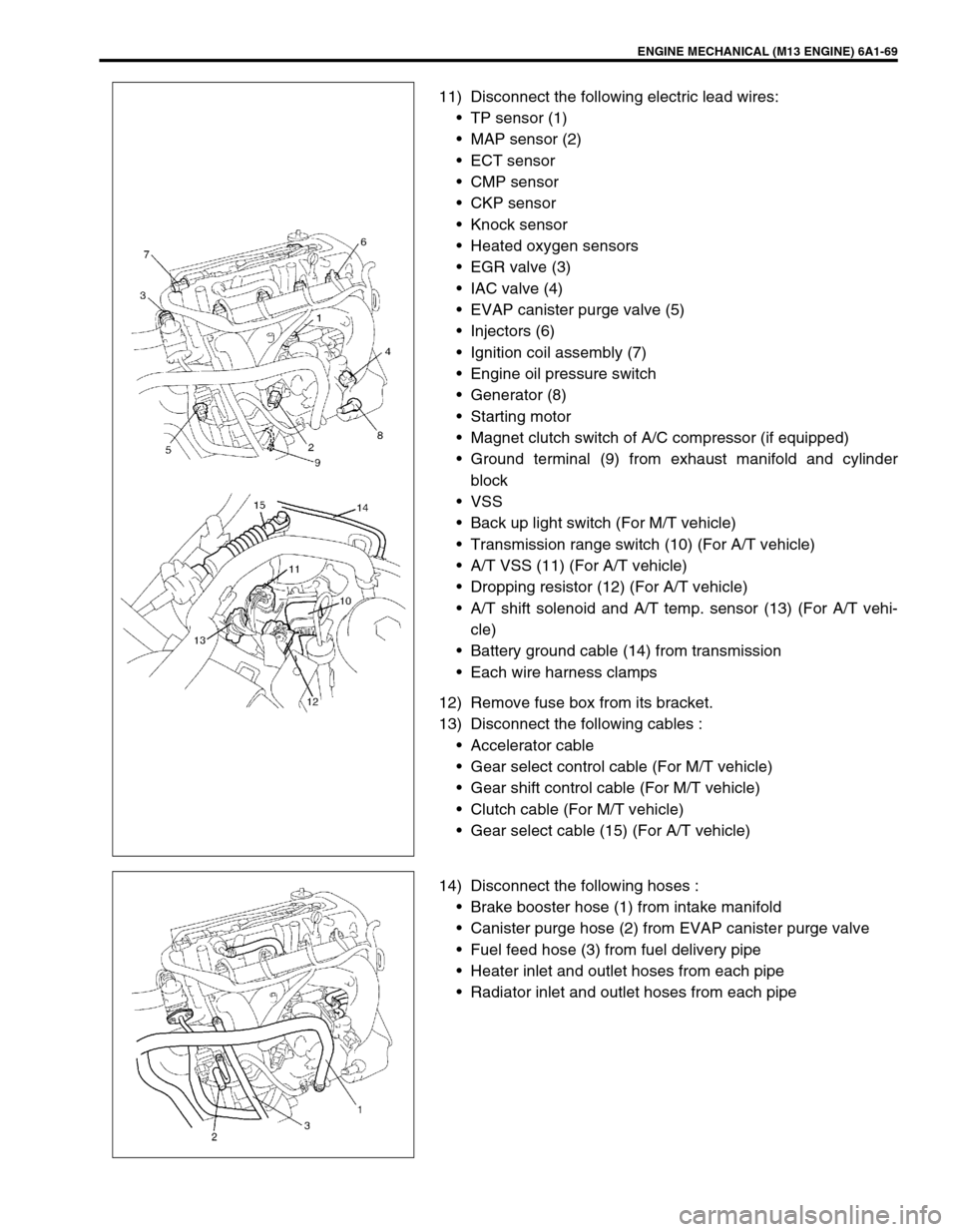
11) Disconnect the following electric lead wires:
TP sensor (1)
MAP sensor (2)
ECT sensor
CMP sensor
CKP sensor
Knock sensor
Heated oxygen sensors
EGR valve (3)
IAC valve (4)
EVAP canister purge valve (5)
Injectors (6)
Ignition coil assembly (7)
Engine oil pressure switch
Generator (8)
Starting motor
Magnet clutch switch of A/C compressor (if equipped)
Ground terminal (9) from exhaust manifold and cylinder
block
VSS
Back up light switch (For M/T vehicle)
Transmission range switch (10) (For A/T vehicle)
A/T VSS (11) (For A/T vehicle)
Dropping resistor (12) (For A/T vehicle)
A/T shift solenoid and A/T temp. sensor (13) (For A/T vehi-
cle)
Battery ground cable (14) from transmission
Each wire harness clamps
12) Remove fuse box from its bracket.
13) Disconnect the following cables :
Accelerator cable
Gear select control cable (For M/T vehicle)
Gear shift control cable (For M/T vehicle)
Clutch cable (For M/T vehicle)
Gear select cable (15) (For A/T vehicle)
14) Disconnect the following hoses :
Brake booster hose (1) from intake manifold
Canister purge hose (2) from EVAP canister purge valve
Fuel feed hose (3) from fuel delivery pipe
Heater inlet and outlet hoses from each pipe
Radiator inlet and outlet hoses from each pipe
Page 587 of 698
6A1-86 ENGINE MECHANICAL (M13 ENGINE)
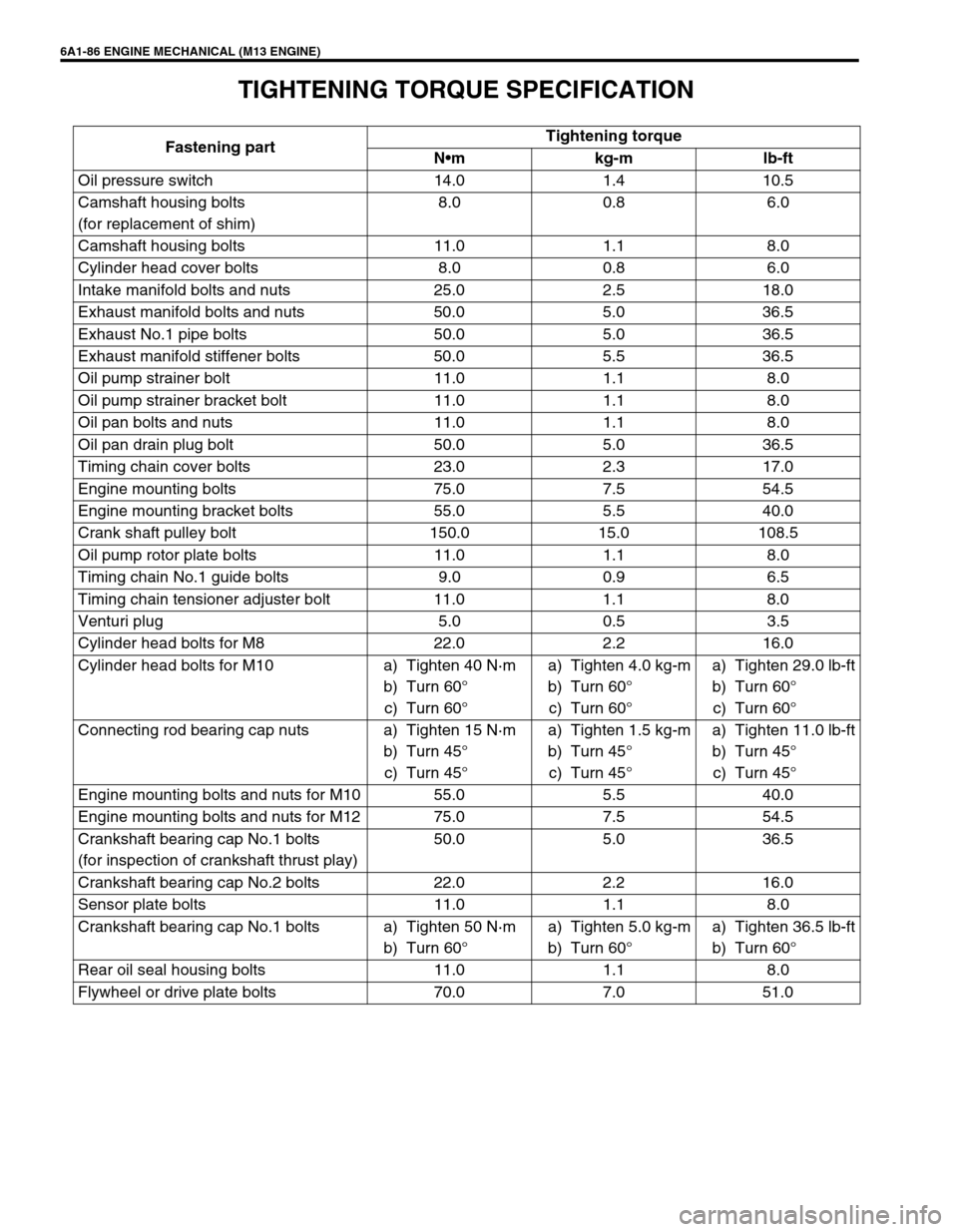
TIGHTENING TORQUE SPECIFICATION
Fastening partTightening torque
Nm kg-m lb-ft
Oil pressure switch 14.0 1.4 10.5
Camshaft housing bolts
(for replacement of shim)8.0 0.8 6.0
Camshaft housing bolts 11.0 1.1 8.0
Cylinder head cover bolts 8.0 0.8 6.0
Intake manifold bolts and nuts 25.0 2.5 18.0
Exhaust manifold bolts and nuts 50.0 5.0 36.5
Exhaust No.1 pipe bolts 50.0 5.0 36.5
Exhaust manifold stiffener bolts 50.0 5.5 36.5
Oil pump strainer bolt 11.0 1.1 8.0
Oil pump strainer bracket bolt 11.0 1.1 8.0
Oil pan bolts and nuts 11.0 1.1 8.0
Oil pan drain plug bolt 50.0 5.0 36.5
Timing chain cover bolts 23.0 2.3 17.0
Engine mounting bolts 75.0 7.5 54.5
Engine mounting bracket bolts 55.0 5.5 40.0
Crank shaft pulley bolt 150.0 15.0 108.5
Oil pump rotor plate bolts 11.0 1.1 8.0
Timing chain No.1 guide bolts 9.0 0.9 6.5
Timing chain tensioner adjuster bolt 11.0 1.1 8.0
Venturi plug 5.0 0.5 3.5
Cylinder head bolts for M8 22.0 2.2 16.0
Cylinder head bolts for M10 a) Tighten 40 N·m
b) Turn 60°
c) Turn 60°a) Tighten 4.0 kg-m
b) Turn 60°
c) Turn 60°a) Tighten 29.0 lb-ft
b) Turn 60°
c) Turn 60°
Connecting rod bearing cap nuts a) Tighten 15 N·m
b) Turn 45°
c) Turn 45°a) Tighten 1.5 kg-m
b) Turn 45°
c) Turn 45°a) Tighten 11.0 lb-ft
b) Turn 45°
c) Turn 45°
Engine mounting bolts and nuts for M10 55.0 5.5 40.0
Engine mounting bolts and nuts for M12 75.0 7.5 54.5
Crankshaft bearing cap No.1 bolts
(for inspection of crankshaft thrust play)50.0 5.0 36.5
Crankshaft bearing cap No.2 bolts 22.0 2.2 16.0
Sensor plate bolts 11.0 1.1 8.0
Crankshaft bearing cap No.1 bolts a) Tighten 50 N·m
b) Turn 60°a) Tighten 5.0 kg-m
b) Turn 60°a) Tighten 36.5 lb-ft
b) Turn 60°
Rear oil seal housing bolts 11.0 1.1 8.0
Flywheel or drive plate bolts 70.0 7.0 51.0
Page 588 of 698
ENGINE MECHANICAL (M13 ENGINE) 6A1-87
SPECIAL TOOL
09911-97720 09911-97820 09913-75520 09915-47330
Oil seal guide Oil seal installer Bearing installer Oil filter wrench
09915-64510-001 09915-64510-002 09915-64530 09915-67010
Compression gauge Connector Hose Attachment
09915-67310 09915-77310 09915-78211 09916-14510
Vacuum gauge Oil pressure gauge Oil pressure gauge
attachmentValve lifer
09916-14910 09916-34542 09916-34550 09916-37320
Valve lifer attachment Reamer handle Reamer (5.5 mm) Reamer (10.5 mm)
Page 595 of 698
6B-6 ENGINE COOLING
MAINTENANCE
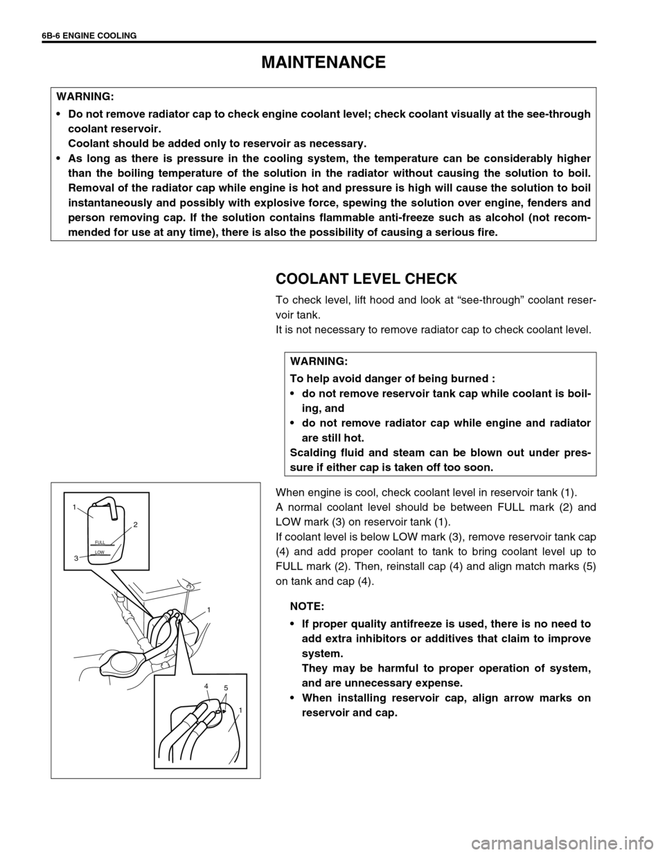
COOLANT LEVEL CHECK
To check level, lift hood and look at “see-through” coolant reser-
voir tank.
It is not necessary to remove radiator cap to check coolant level.
When engine is cool, check coolant level in reservoir tank (1).
A normal coolant level should be between FULL mark (2) and
LOW mark (3) on reservoir tank (1).
If coolant level is below LOW mark (3), remove reservoir tank cap
(4) and add proper coolant to tank to bring coolant level up to
FULL mark (2). Then, reinstall cap (4) and align match marks (5)
on tank and cap (4). WARNING:
Do not remove radiator cap to check engine coolant level; check coolant visually at the see-through
coolant reservoir.
Coolant should be added only to reservoir as necessary.
As long as there is pressure in the cooling system, the temperature can be considerably higher
than the boiling temperature of the solution in the radiator without causing the solution to boil.
Removal of the radiator cap while engine is hot and pressure is high will cause the solution to boil
instantaneously and possibly with explosive force, spewing the solution over engine, fenders and
person removing cap. If the solution contains flammable anti-freeze such as alcohol (not recom-
mended for use at any time), there is also the possibility of causing a serious fire.
WARNING:
To help avoid danger of being burned :
do not remove reservoir tank cap while coolant is boil-
ing, and
do not remove radiator cap while engine and radiator
are still hot.
Scalding fluid and steam can be blown out under pres-
sure if either cap is taken off too soon.
NOTE:
If proper quality antifreeze is used, there is no need to
add extra inhibitors or additives that claim to improve
system.
They may be harmful to proper operation of system,
and are unnecessary expense.
When installing reservoir cap, align arrow marks on
reservoir and cap.
LOW FULL
5 41
1 32 1