Page 119 of 698

3A-2 FRONT END ALIGNMENT
GENERAL DESCRIPTION
Front alignment refers to the angular relationship between the
front wheels, the front suspension attaching parts and the ground.
Generally, the only adjustment required for front alignment is toe
setting.
Camber and caster can’t be adjusted. Therefore, should camber
or caster be out of specification due to the damage caused by
hazardous road conditions or collision, whether the damage is in
body or in suspension should be determined. If the body is dam-
aged, it should be repaired and if suspension is damaged, it
should be replaced.
TOE SETTING
Toe is the turning in or out of the front wheels. The purpose of a
toe specification is to ensure parallel rolling of the front wheels
(Excessive toe-in or toe-out may increase tire wear).
Toe-in
“B”-“A” : 0 ± 1 mm (0 ± 0.039 in.)
For adjusting toe setting, refer to “TOE ADJUSTMENT” in this
section.
CAMBER
Camber is the tilting of the front wheels from the vertical, as
viewed from the front of the vehicle. When the wheels tilt outward
at the top, the camber is positive. When the wheels tilt inward at
the top, the camber is negative. The amount of tilt is measured in
degrees.
Camber “C”
2WD vehicle : –0° 20’ ± 1°
4WD vehicle : 0° ± 1°
ALIGNMENT SERVICE DATA (REFERENCE)
Caster
2WD vehicle : 3° 25’ ± 2°
4WD vehicle : 3° 35’ ± 2°
Kingpin inclination
2WD vehicle : 12° 40’ ± 2°
4WD vehicle : 12° 15’ ± 2° NOTE:
Toe-in value was measured by using a toe-in gauge.
[A]: Wheel top view
1. Forward
“A”
“B”1 [A]
1. Body center [A]: Front view
2. Center line of wheel
2
1
90
o
C [A]
Page 120 of 698

FRONT END ALIGNMENT 3A-3
DIAGNOSIS
DIAGNOSIS TABLE
For the details, refer to Section 3.
PRELIMINARY CHECKS PRIOR TO ADJUSTING FRONT ALIGNMENT
Steering and vibration complaints are not always the result of improper alignment. An additional item to be
checked is the possibility of tire lead due to worn or improperly manufactured tires. “Lead” is the deviation of the
vehicle from a straight path on a level road without hand pressure on the steering wheel. Procedure for deter-
mining the presence of a tire lead problem contains in SECTION 3. Before making any adjustment affecting toe
setting, the following checks and inspections should be made to ensure correctness of alignment readings and
alignment adjustments:
1) Check all tires for proper inflation pressures and approximately the same tread wear.
2) Check for loose of ball joints. Check tie rod ends; if excessive looseness is noted, it must be corrected
before adjusting.
3) Check for run-out of wheels and tires.
4) Check vehicle trim heights; if out of limits and a correction is to be made, it must be made before adjusting
toe.
5) Check for loose of suspension arms.
6) Check for loose or missing stabilizer bar attachments.
7) Consideration must be given to excess loads, such as tool boxes. If this excess load is normally carried in
vehicle, it should remain in vehicle during alignment checks.
8) Consider condition of equipment being used to check alignment and follow manufacturer's instructions.
9) Regardless of equipment used to check alignment, vehicle must be on a level surface both fore and aft and
transversely.
TOE ADJUSTMENT
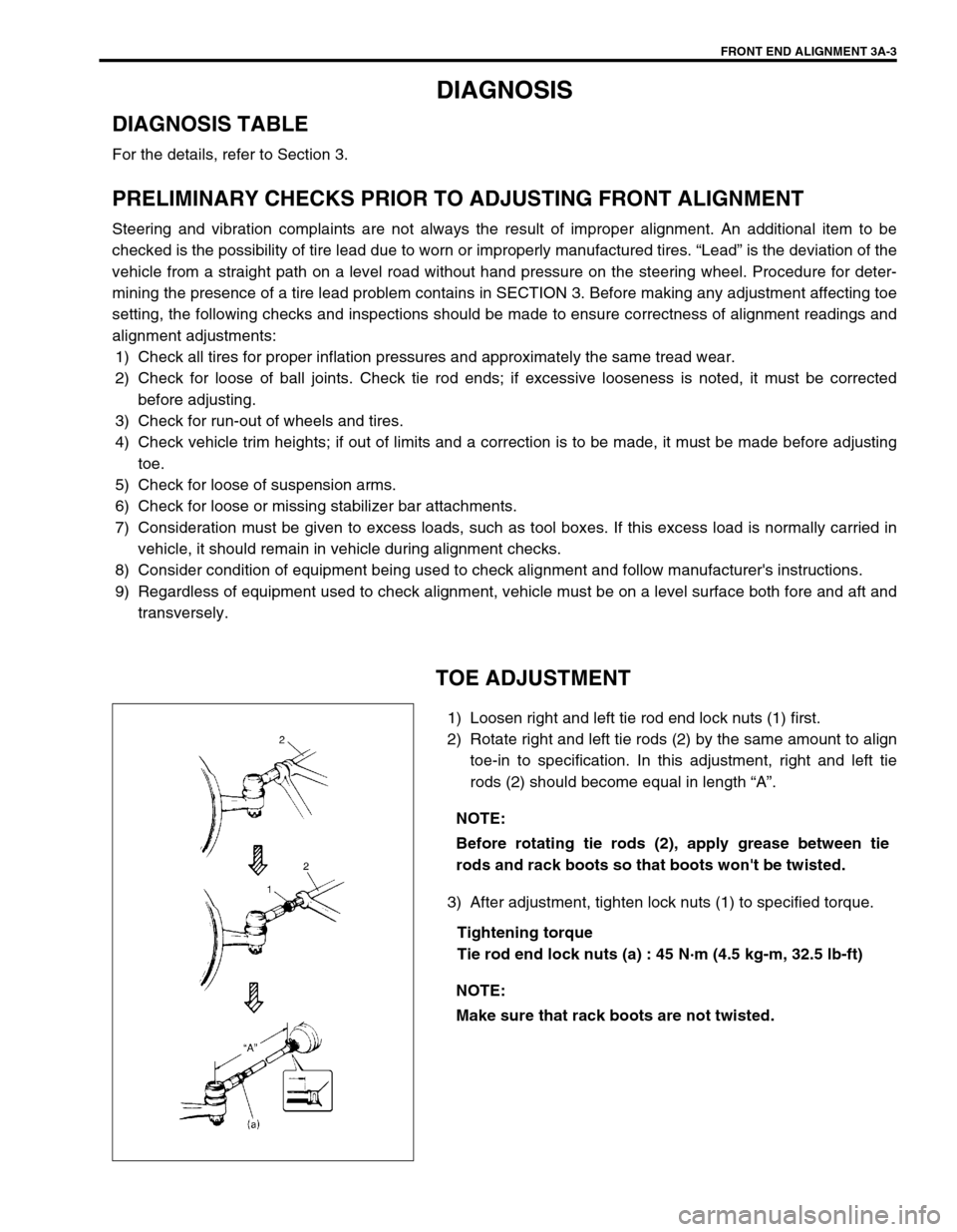
1) Loosen right and left tie rod end lock nuts (1) first.
2) Rotate right and left tie rods (2) by the same amount to align
toe-in to specification. In this adjustment, right and left tie
rods (2) should become equal in length “A”.
3) After adjustment, tighten lock nuts (1) to specified torque.
Tightening torque
Tie rod end lock nuts (a) : 45 N·m (4.5 kg-m, 32.5 lb-ft) NOTE:
Before rotating tie rods (2), apply grease between tie
rods and rack boots so that boots won't be twisted.
NOTE:
Make sure that rack boots are not twisted.
Page 121 of 698

3A-4 FRONT END ALIGNMENT
CAMBER AND CASTER CHECK AND
ADJUSTMENT
Should camber or caster be found out of specifications upon
inspection, locate its cause first.
If it is in damaged, loose, bent, dented or worn suspension parts,
they should be replaced.
If it is in vehicle body, repair it so as to attain specifications.
STEERING ANGLE CHECK AND ADJUST-
MENT
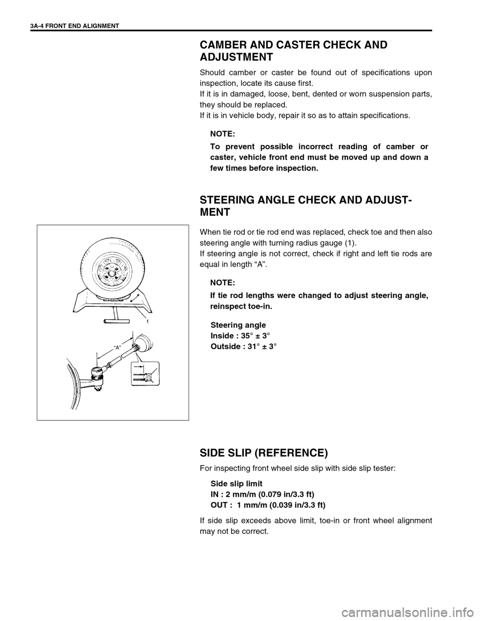
When tie rod or tie rod end was replaced, check toe and then also
steering angle with turning radius gauge (1).
If steering angle is not correct, check if right and left tie rods are
equal in length “A”.
Steering angle
Inside : 35° ± 3°
Outside : 31° ± 3°
SIDE SLIP (REFERENCE)
For inspecting front wheel side slip with side slip tester:
Side slip limit
IN : 2 mm/m (0.079 in/3.3 ft)
OUT : 1 mm/m (0.039 in/3.3 ft)
If side slip exceeds above limit, toe-in or front wheel alignment
may not be correct.NOTE:
To prevent possible incorrect reading of camber or
caster, vehicle front end must be moved up and down a
few times before inspection.
NOTE:
If tie rod lengths were changed to adjust steering angle,
reinspect toe-in.
Page 123 of 698
3B-2 MANUAL RACK AND PINION
GENERAL DESCRIPTION
The rack and pinion steering system consists of two components, the rack (2) and the pinion (1). When the
steering wheel (3) is turned, the motion is transmitted to the steering shaft joint (4) and then to the pinion.
Since the pinion teeth mesh with teeth on rack, the motion is further transferred to the rack and changed to lin-
ear motion. The force is then transmitted through the tie rods (5) to the steering knuckles (6) which turn wheels.
7. Steering shaft
8. Steering gear case
[A]: Rack and Pinion
Page 125 of 698
3B-4 MANUAL RACK AND PINION
STEERING WHEEL CHECK
Check steering wheel for play and rattle, holding vehicle in
straight forward condition on the ground.
Steering wheel play
“a” : 0 – 30 mm (0 – 1.1 in.)
If steering wheel play is not within specification, inspect as follows
and replace if found defective.
Tie-rod end ball stud for wear (ball stud should move when
more than 2 kg-cm torque is applied.)
Lower ball joint for wear
Steering shaft joint for wear
Steering pinion or rack gear for wear or breakage
Each part for looseness
ON-VEHICLE SERVICE
LUBRICATION
When inner parts of the steering gear case were disassembled, they should be washed clean before reassem-
bly. It is recommended to use the grease as given below where grease application is indicated in the text.
✱
✱✱ ✱ SUZUKI SUPER GREASE (E) 99000-25050, or Lithium grease
(applicable for –40°C ~ 130°C or 104°F ~ 266°F)
Page 127 of 698
3B-6 MANUAL RACK AND PINION
TIE ROD END
REMOVAL
1) Hoist vehicle and remove wheel.
2) Remove split pin (1) and tie rod end castle nut (3) from steer-
ing knuckle (2).
3) Disconnect tie rod end from knuckle, using special tool.
Special tool
(A) : 09913-65210
4) For ease of adjustment after installation, make marking (2) of
tie rod end lock nut (3) position on tie rod end thread. Then
loosen lock nut and remove tie rod end (4) from tie rod (1).
INSTALLATION
1) Install tie rod end lock nut (3) and tie rod end (4) to tie rod
(1). Align lock nut with mar (2) on tie rod thread.
5. Knuckle
6. Castle nut
7. Split pin
Page 128 of 698

MANUAL RACK AND PINION 3B-7
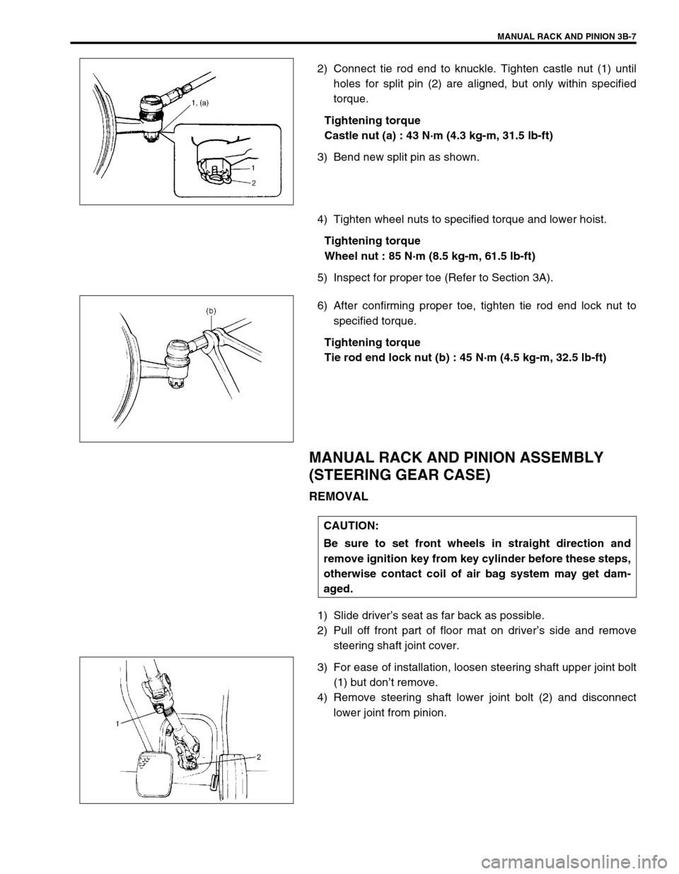
2) Connect tie rod end to knuckle. Tighten castle nut (1) until
holes for split pin (2) are aligned, but only within specified
torque.
Tightening torque
Castle nut (a) : 43 N·m (4.3 kg-m, 31.5 lb-ft)
3) Bend new split pin as shown.
4) Tighten wheel nuts to specified torque and lower hoist.
Tightening torque
Wheel nut : 85 N·m (8.5 kg-m, 61.5 lb-ft)
5) Inspect for proper toe (Refer to Section 3A).
6) After confirming proper toe, tighten tie rod end lock nut to
specified torque.
Tightening torque
Tie rod end lock nut (b) : 45 N·m (4.5 kg-m, 32.5 lb-ft)
MANUAL RACK AND PINION ASSEMBLY
(STEERING GEAR CASE)
REMOVAL
1) Slide driver’s seat as far back as possible.
2) Pull off front part of floor mat on driver’s side and remove
steering shaft joint cover.
3) For ease of installation, loosen steering shaft upper joint bolt
(1) but don’t remove.
4) Remove steering shaft lower joint bolt (2) and disconnect
lower joint from pinion.
CAUTION:
Be sure to set front wheels in straight direction and
remove ignition key from key cylinder before these steps,
otherwise contact coil of air bag system may get dam-
aged.
Page 129 of 698
3B-8 MANUAL RACK AND PINION
5) Hoist vehicle and remove both wheels.
6) Remove split pins (3) and tie rod castle nuts (2) from both
knuckles (1).
7) Disconnect both tie rod ends (2) from knuckles (1), using
special tool.
Special tool
(A) : 09913-65210
8) Remove exhaust No.1 pipe (1).
9) For ease of adjustment after installation, make marking of tie
rod end lock nut position on tie rod end thread. Then loosen
lock nut and remove tie rod end.
10) Remove steering gear case mount bolts (1) and gear case
brackets, then remove gear case (2).
1
NOTE:
For right-hand steering 4WD vehicle, before removing
steering gear case, remove transfer assembly referring
to Section 7D if necessary.
2
1