2000 SUZUKI SWIFT maintenance
[x] Cancel search: maintenancePage 51 of 698

0B-22 MAINTENANCE AND LUBRICATION
Page 175 of 698

3C-2 STEERING WHEEL AND COLUMN
GENERAL DESCRIPTION
STEERING COLUMN
This double tube type steering column has following three important features in addition to the steering function
:
The column is energy absorbing, designed to compress in a front-end collision.
The ignition switch and lock are mounted conveniently on this column.
With the column mounted lock, the ignition and steering operations can be locked to inhibit theft of the vehi-
cle.
To insure the energy absorbing action, it is important that only the specified screws, bolts, and nuts be used as
designated and that they are tightened to the specified torque.
When the column assembly is removed from the vehicle, special care must be taken in handling it. Use of a
steering wheel puller other than the one recommended in this manual or a sharp blow on the end of the steering
shaft, leaning on the assembly, or dropping the assembly could shear the plastic shear pins which maintain col-
umn length and position.
STEERING WHEEL AND DRIVER AIR BAG (INFLATOR) MODULE
The driver air bag (inflator) module is one of the supplemental restraint (air bag) system components and is
mounted to the center of the steering wheel. During certain frontal crashes, the air bag system supplements the
restraint of the driver’s and passenger’s seat belts by deploying the air bags.
The air bag (inflator) module should be handled with care to prevent accidental deployment. When servicing, be
sure to observe all WARNINGS and CAUTIONS and “SERVICE PRECAUTIONS” under “ON-VEHICLE SER-
VICE” in Section 10B.
DIAGNOSIS
For maintenance service of the steering wheel and column, refer to Section 0B.
For diagnosis of the steering wheel and column, refer to Section 3.
For diagnosis of the air bag system, refer to Section 10B.
INSPECTION AND REPAIR REQUIRED AFTER ACCIDENT
After an accident, whether the air bag has been deployed or not, be sure to perform checks, inspections and
repairs described under “CHECKING STEERING COLUMN ASSEMBLY AND LOWER SHAFT FOR ACCI-
DENT DAMAGE” as well as “REPAIRS AND INSPECTIONS REQUIRED AFTER ACCIDENT” under “DIAGNO-
SIS” in Section 10B.
Page 246 of 698

WHEELS AND TIRES 3F-1
6F1
6F2
6G
3F
8A
8B
8C
8D
8E
9
10
10A
10B
SECTION 3F
WHEELS AND TIRES
CONTENTS
GENERAL DESCRIPTION ............................... 3F-2
TIRES ............................................................ 3F-2
WHEELS ....................................................... 3F-2
REPLACEMENT TIRES ................................ 3F-2
REPLACEMENT WHEELS ........................... 3F-2
HOW TO MEASURE WHEEL RUNOUT... 3F-3
METRIC LUG NUTS AND WHEEL
STUDS ...................................................... 3F-3
DIAGNOSIS ...................................................... 3F-3
DIAGNOSIS TABLE ...................................... 3F-3
BALANCING WHEELS ................................. 3F-3
GENERAL BALANCE PROCEDURES ......... 3F-4
OFF-VEHICLE BALANCING ..................... 3F-4
ON-VEHICLE BALANCING....................... 3F-4MAINTENANCE AND MINOR
ADJUSTMENTS ............................................... 3F-5
WHEEL MAINTENANCE .............................. 3F-5
WHEEL ATTACHING STUDS .................. 3F-5
MATCHED TIRES AND WHEELS ............ 3F-5
TIRE MAINTENANCE................................... 3F-5
TIRE PLACARD ........................................ 3F-5
INFLATION OF TIRES .............................. 3F-6
TIRE ROTATION ...................................... 3F-6
ON-VEHICLE SERVICE ................................... 3F-7
WHEEL ......................................................... 3F-7
TIRE .............................................................. 3F-8
MOUNTING AND DISMOUNTING ........... 3F-8
REPAIR ..................................................... 3F-8
NOTE:
All wheel fasteners are important attaching parts in that they could affect the performance of vital
parts and systems, and/or could result in major repair expense. They must be replaced with one of the
same part number or with an equivalent part if replacement becomes necessary. Do not use a replace-
ment part of lesser quality or substitute design. Torque values must be used as specified during reas-
sembly to assure proper retention of all parts.
There is to be no welding as it may result in extensive damage and weakening of the metal.
Page 250 of 698

WHEELS AND TIRES 3F-5
MAINTENANCE AND MINOR ADJUSTMENTS
WHEEL MAINTENANCE
Wheel repairs that use welding, heating, or peening are not approved. All damaged wheels should be replaced.
WHEEL ATTACHING STUDS
If a broken stud is found, see Section 3E (rear) or Section 3D (front) for Note and Replacement procedure.
MATCHED TIRES AND WHEELS
Tires and wheels are match mounted at the assembly plant.
This means that the radially stiffest part of the tire, or “high spot”,
is matched to the smallest radius or “low spot” of the wheel.
This is done to provide the smoothest possible ride.
The “high spot” of the tire is originally marked by paint dot (1) on
the outboard sidewall. This paint dot will eventually wash off the
tire.
The “ow spot” of the wheel is originally marked by paint dot (2) on
the wheel rim-flange. Properly assembled, the wheel rims’ paint
dot should be aligned with the tires’ paint dot as shown in left fig-
ure.
Whenever a tire is dismounted from its wheel, it should be
remounted so that the tire and wheel are matched. If the tire’s
paint dot cannot be located, a line should be scribed on the tire
and wheel before dismounting to assure that it is remounted in
the same position.
TIRE MAINTENANCE
TIRE PLACARD
The “Tire Placard” is located on the left door (right door for right-hand side steering vehicle) lock pillar and
should be referred to tire information.
The placard lists the maximum load, tire size and cold tire pressure where applicable.
NOTE:
Whether rim size and/or maximum load are listed or not depends on regulations of each country.
Page 270 of 698

PROPELLER SHAFTS 4B-1
6F1
6F2
6G
6H
6K
7A
7A1
7B1
7C1
7D
7E
7F
4B
8D
8E
9
10
10A
10B
SECTION 4B
PROPELLER SHAFTS
CONTENTS
GENERAL DESCRIPTION .............................. 4B-1
DIAGNOSIS ..................................................... 4B-1
DIAGNOSIS TABLE ..................................... 4B-1PROPELLER SHAFT JOINT CHECK.......... 4B-2
ON-VEHICLE SERVICE .................................. 4B-2
TIGHTENING TORQUE SPECIFICATION...... 4B-4
GENERAL DESCRIPTION
Most universal and constant velocity joints require no maintenance. They are lubricated for life and can not be
lubricated on the vehicle. If universal and constant velocity joints becomes noisy or worn, it must be replace.
The propeller shaft is a balanced unit. Handle it carefully so that balance can be maintained.
DIAGNOSIS
DIAGNOSIS TABLE
Condition Possible Cause Correction
Abnormal noise
Loose universal joint bolt Tighten universal joint bolt.
Spider bearing worn out or stuck Replace.
Wear spider Replace propeller shaft.
Vibration
Performed propeller shaft Replace.
Page 282 of 698

BRAKES 5-9
EXCESSIVE PEDAL TRAVEL INSPECTION
1) Start engine.
2) Depress brake pedal a few times.
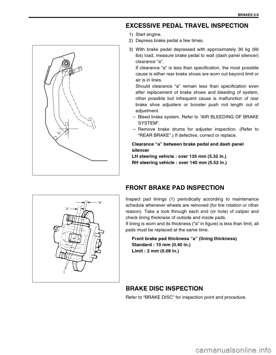
3) With brake pedal depressed with approximately 30 kg (66
lbs) load, measure brake pedal to wall (dash panel silencer)
clearance “a”.
If clearance “a” is less than specification, the most possible
cause is either rear brake shoes are worn out beyond limit or
air is in lines.
Should clearance “a” remain less than specification even
after replacement of brake shoes and bleeding of system,
other possible but infrequent cause is malfunction of rear
brake shoe adjusters or booster push rod length out of
adjustment.
–Bleed brake system. Refer to “AIR BLEEDING OF BRAKE
SYSTEM”.
–Remove brake drums for adjuster inspection. (Refer to
“REAR BRAKE”.) If defective, correct or replace.
Clearance “a” between brake pedal and dash panel
silencer
LH steering vehicle : over 135 mm (5.32 in.)
RH steering vehicle : over 140 mm (5.52 in.)
FRONT BRAKE PAD INSPECTION
Inspect pad linings (1) periodically according to maintenance
schedule whenever wheels are removed (for tire rotation or other
reason). Take a look through each end (or hole) of caliper and
check lining thickness of outside and inside pads.
If lining is worn and its thickness (“a” in figure) is less than limit, all
pads must be replaced at the same time.
Front brake pad thickness “a” (lining thickness)
Standard : 10 mm (0.40 in.)
Limit : 2 mm (0.08 in.)
BRAKE DISC INSPECTION
Refer to “BRAKE DISC” for inspection point and procedure.
“a”
Page 590 of 698

ENGINE COOLING 6B-1
6B
SECTION 6B
ENGINE COOLING
CONTENTS
GENERAL DESCRIPTION ...............................6B-2
COOLING SYSTEM CIRCULATION............. 6B-2
COOLANT ..................................................... 6B-3
DIAGNOSIS ......................................................6B-4
DIAGNOSIS TABLE ...................................... 6B-4
SYSTEM CIRCUIT ........................................ 6B-5
SYSTEM CIRCUIT INSPECTION ................. 6B-5
MAINTENANCE................................................6B-6
COOLANT LEVEL CHECK ........................... 6B-6
ENGINE COOLING SYSTEM
INSPECTION AND SERVICE ....................... 6B-7
COOLING SYSTEM FLUSH AND REFILL ... 6B-7
WATER PUMP/GENERATOR DRIVE
BELT TENSION INSPECTION AND
ADJUSTMENT .............................................. 6B-9
ON-VEHICLE SERVICE .................................6B-10SYSTEM COMPONENTS .......................... 6B-10
COOLING SYSTEM DRAINING ................. 6B-11
COOLING SYSTEM REFILL ...................... 6B-11
COOLING WATER PIPES OR HOSES ...... 6B-12
THERMOSTAT ........................................... 6B-12
RADIATOR ................................................. 6B-14
RADIATOR AND CONDENSER
COOLING FAN ........................................... 6B-15
RADIATOR AND CONDENSER
COOLING FAN RELAY .............................. 6B-15
WATER PUMP/GENERATOR
DRIVE BELT ............................................... 6B-15
WATER PUMP............................................ 6B-16
ECT SENSOR............................................. 6B-18
REQUIRED SERVICE MATERIAL................. 6B-18
TIGHTENING TORQUE SPECIFICATION..... 6B-18
Page 595 of 698

6B-6 ENGINE COOLING
MAINTENANCE
COOLANT LEVEL CHECK
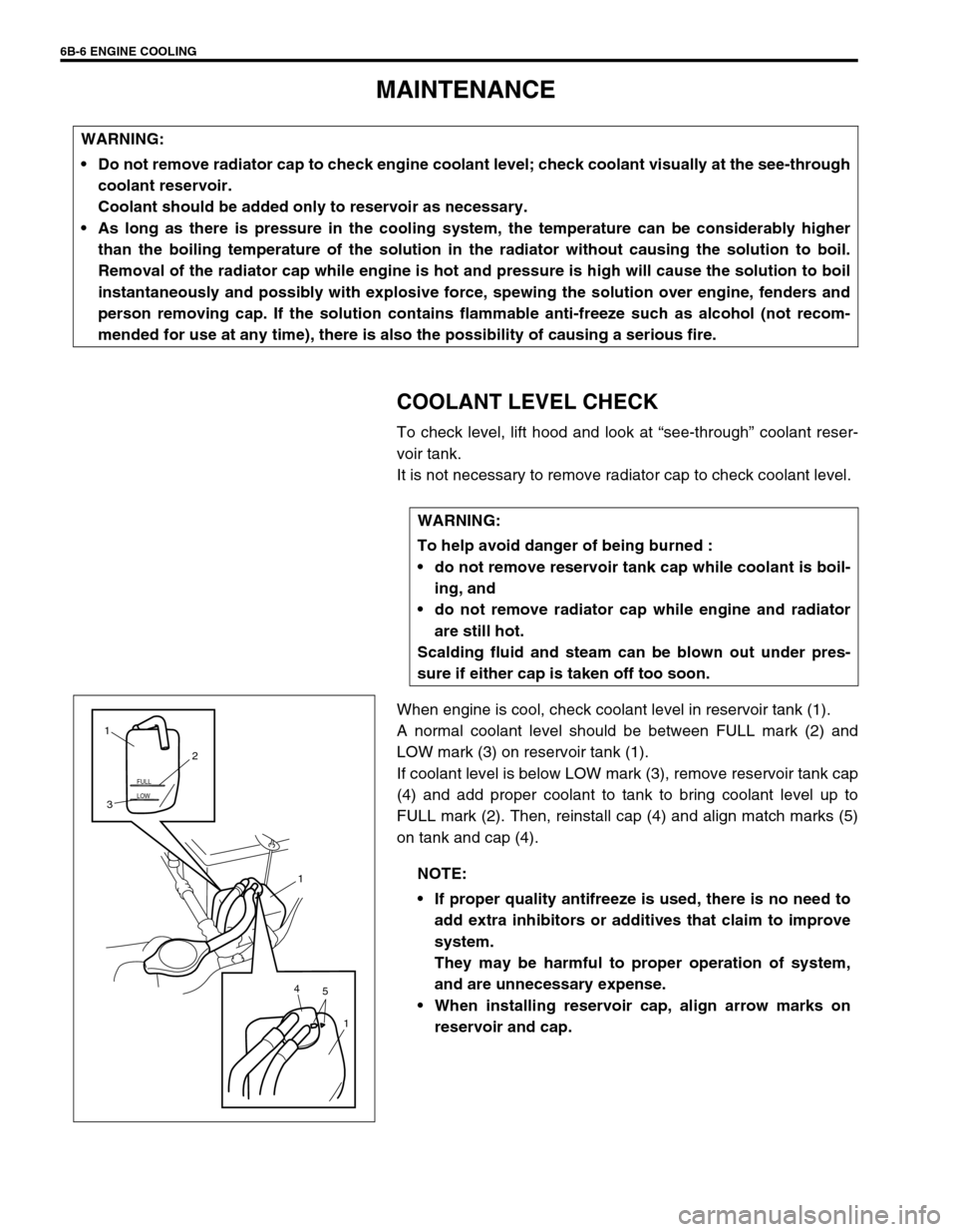
To check level, lift hood and look at “see-through” coolant reser-
voir tank.
It is not necessary to remove radiator cap to check coolant level.
When engine is cool, check coolant level in reservoir tank (1).
A normal coolant level should be between FULL mark (2) and
LOW mark (3) on reservoir tank (1).
If coolant level is below LOW mark (3), remove reservoir tank cap
(4) and add proper coolant to tank to bring coolant level up to
FULL mark (2). Then, reinstall cap (4) and align match marks (5)
on tank and cap (4). WARNING:
Do not remove radiator cap to check engine coolant level; check coolant visually at the see-through
coolant reservoir.
Coolant should be added only to reservoir as necessary.
As long as there is pressure in the cooling system, the temperature can be considerably higher
than the boiling temperature of the solution in the radiator without causing the solution to boil.
Removal of the radiator cap while engine is hot and pressure is high will cause the solution to boil
instantaneously and possibly with explosive force, spewing the solution over engine, fenders and
person removing cap. If the solution contains flammable anti-freeze such as alcohol (not recom-
mended for use at any time), there is also the possibility of causing a serious fire.
WARNING:
To help avoid danger of being burned :
do not remove reservoir tank cap while coolant is boil-
ing, and
do not remove radiator cap while engine and radiator
are still hot.
Scalding fluid and steam can be blown out under pres-
sure if either cap is taken off too soon.
NOTE:
If proper quality antifreeze is used, there is no need to
add extra inhibitors or additives that claim to improve
system.
They may be harmful to proper operation of system,
and are unnecessary expense.
When installing reservoir cap, align arrow marks on
reservoir and cap.
LOW FULL
5 41
1 32 1