Page 266 of 698

FRONT DRIVE SHAFT 4A-13
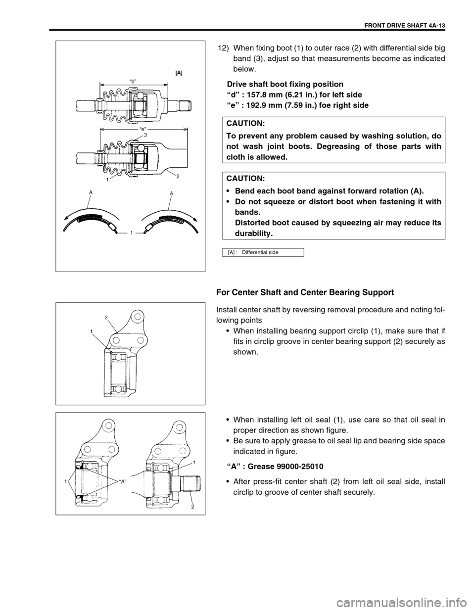
12) When fixing boot (1) to outer race (2) with differential side big
band (3), adjust so that measurements become as indicated
below.
Drive shaft boot fixing position
“d” : 157.8 mm (6.21 in.) for left side
“e” : 192.9 mm (7.59 in.) foe right side
For Center Shaft and Center Bearing Support
Install center shaft by reversing removal procedure and noting fol-
lowing points
When installing bearing support circlip (1), make sure that if
fits in circlip groove in center bearing support (2) securely as
shown.
When installing left oil seal (1), use care so that oil seal in
proper direction as shown figure.
Be sure to apply grease to oil seal lip and bearing side space
indicated in figure.
“A” : Grease 99000-25010
After press-fit center shaft (2) from left oil seal side, install
circlip to groove of center shaft securely. CAUTION:
To prevent any problem caused by washing solution, do
not wash joint boots. Degreasing of those parts with
cloth is allowed.
CAUTION:
Bend each boot band against forward rotation (A).
Do not squeeze or distort boot when fastening it with
bands.
Distorted boot caused by squeezing air may reduce its
durability.
[A] : Differential side
Page 267 of 698
4A-14 FRONT DRIVE SHAFT
When installing right oil seal (1), use care so that oil seal in
proper direction as shown figure.
Be sure apply grease to oil seal lip and bearing side space
indicated in figure.
“A” : Grease 99000-25010
INSTALLATION
Install drive shaft assembly by reversing removal procedure and
noting following points.
Clean front wheel bearing oil seal (1) and then apply grease.
Replace it if required.
“A” : Grease 99000-25010
CAUTION:
To avoid excessive expansion of boot and consequen-
tial disconnection of joint in boot, do not pull differen-
tial side joint housing.
Protect oil seals and boots from any damage, prevent-
ing them from unnecessary contact while installing
drive shaft.
Do not hit joint boot with hammer. Inserting joint only
by hands is allowed.
Make sure that differential side joint is inserted fully
and its snap ring is seated as it was.
Page 290 of 698
BRAKES 5-17
FRONT BRAKE
BRAKE PAD
REMOVAL
1) Loosen wheel nuts and with vehicle lifted up, remove
wheels.
2) Remove caliper pin bolts (1).
1. Brake caliper carrier 9. Bleeder plug cap
2. Boot 10. Pad spring
3. Caliper 11. Anti noise shim
4. Disc brake piston 12. Caliper pin bolt
5. Piston seal
: Apply fluid (Brake, power steering or automatic transmission fluid).13. Brake disc
6. Cylinder boot
: Apply fluid (Brake, power steering or automatic transmission fluid).14. Slide pin
: Apply lithium grease (99000-25010).
7. Brake pad Tightening torque
8. Bleeder plugDo not reuse.
9
1
7
13
2
143
1226 N·m(2.6 kg-m)
85 N·m(8.5 kg-m)
8
8.5 N·m(0.85 kg-m)
10
5 4
6
11
Page 293 of 698
5-20 BRAKES
DISASSEMBLY
1) Remove piston with air blown into flexible hose bolt installa-
tion hole.
2) Remove cylinder boot (1).
3) Remove piston seal using a thin blade like a thickness
gauge, etc.
4) Remove bleeder plug and cap from caliper.
INSPECTION
Pin Boot and Cylinder Boot
Check boots for breakage, crack and damage.
If defective, replace.CAUTION:
Clean around caliper with brake fluid before disassem-
bly.
WARNING:
Do not apply too highly compressed air which will cause
piston to jump out of cylinder. Place a cloth (1) to prevent
piston from damage. It should be taken out gradually
with moderately compressed air. Do not place your fin-
gers in front of piston when using compressed air.
CAUTION:
Use care not to cause damage to cylinder boot.
1
CAUTION:
Be careful not to damage inside (bore side) of cylinder.
Page 295 of 698
5-22 BRAKES
b) Before inserting piston (2) into cylinder, install boot (1) onto
piston as shown.
“A” : 1-grooved side directed cylinder side
“B” : 2-grooved side directed pad side
c) Fit boot as it is in figure into boot groove in cylinder with fin-
gers.
d) Insert piston into cylinder by hand and fit boot in boot
groove in piston.
INSTALLATION
1) Connect caliper to flexible hose.
2) Apply grease to slide pin, then install caliper to caliper car-
rier.
3) Torque caliper pin bolts (1) to specification.
Tightening torque
Caliper pin bolts (a) : 26 N·m (2.6 kg-m, 19.0 Ib-ft)
“A”
“B”
NOTE:
Check that boot is fitted in boot groove securely all
around piston.
NOTE:
Make sure that boots are fit into groove securely.