Page 457 of 698

6-88 ENGINE GENERAL INFORMATION AND DIAGNOSIS
DTC P0335 (DTC NO.23) CRANKSHAFT POSITION (CKP) SENSOR CIRCUIT
MALFUNCTION
WIRING DIAGRAM / CIRCUIT DESCRIPTION
REFERENCE
Connect oscilloscope between terminals C42-23 of ECM connector connected to ECM and ground and check
CKP sensor signal.
DTC CONFIRMATION PROCEDURE
1) Clear DTC and crank engine for 2 sec.
2) Select “DTC” mode on scan tool and check DTC.
ECM
5V+B
BLK/RED
YEL/BLK
C42-23
BLK/ORN
C42 (31P) C41 (24P) G02 (17P)1 2 3 4 5 6 7 8 9
10 11 12 13 14 15 16 17 18 19 20 21
22 23 24 25 26 28 27 29 30 315 6
1 2 3 4 5 6 7
11 12
9 10 11 13 12 14 15 16
16 171 2
7 8
13 14 3 4
9 10
15 17 188
19 20 21 22 23 24
DTC DETECTING CONDITION POSSIBLE CAUSE
No CKP sensor signal for 2 seconds at engine crank-
ing.CKP sensor circuit open or short.
Crankshaft timing belt pulley teeth damaged.
CKP sensor malfunction, foreign material being
attached or improper installation.
ECM malfunction.
1. BTDC 5° (Crank angle) [B] : Waveforms at specified idle speed
[A] : Oscilloscope Waveforms [C] : Waveforms at 2000 r/min
Page 527 of 698
6A1-26 ENGINE MECHANICAL (M13 ENGINE)
3) Remove right side engine under cover (1).
4) Remove A/C compressor belt (3) (if equipped).
5) Remove water pump belt (1).
6) Remove water pump pulley (2).
7) Drain engine oil.
8) Remove crankshaft pulley bolt (2).
To lock crankshaft pulley (1), use special tool with it as
shown in figure.
Special tool
(A) : 09917-68221
9) Remove oil pan (1) referring to “OIL PAN AND OIL PUMP
STRAINER”.
10) Remove cylinder head cover referring to “CYLINDER HEAD
COVER”.
Page 530 of 698
ENGINE MECHANICAL (M13 ENGINE) 6A1-29
5) Install cylinder head cover referring to “CYLINDER HEAD
COVER”.
6) Install oil pan (1) referring to “OIL PAN AND OIL PUMP
STRAINER”.
7) Install crankshaft pulley (1). Tighten bolt (2) to specified
torque. To lock crankshaft pulley, use special tool with it as
shown in the figure.
Special tool
(A) : 09917-68221
Tightening torque
Crankshaft pulley bolt (a) : 150 N·m (15.0 kg-m, 108.5 lb-ft)
8) Adjust water pump belt tension referring to Section 0B for
adjusting procedure.
9) Adjust A/C compressor belt tension (if equipped) referring to
Section 1B for adjusting procedure.
10) Install right side engine under cover.
11) Connect disconnected electric lead wires securely.
12) Refill engine with engine oil.
13) Verify that there is no oil leakage and exhaust gas leakage at
each connection.
Page 539 of 698

6A1-38 ENGINE MECHANICAL (M13 ENGINE)
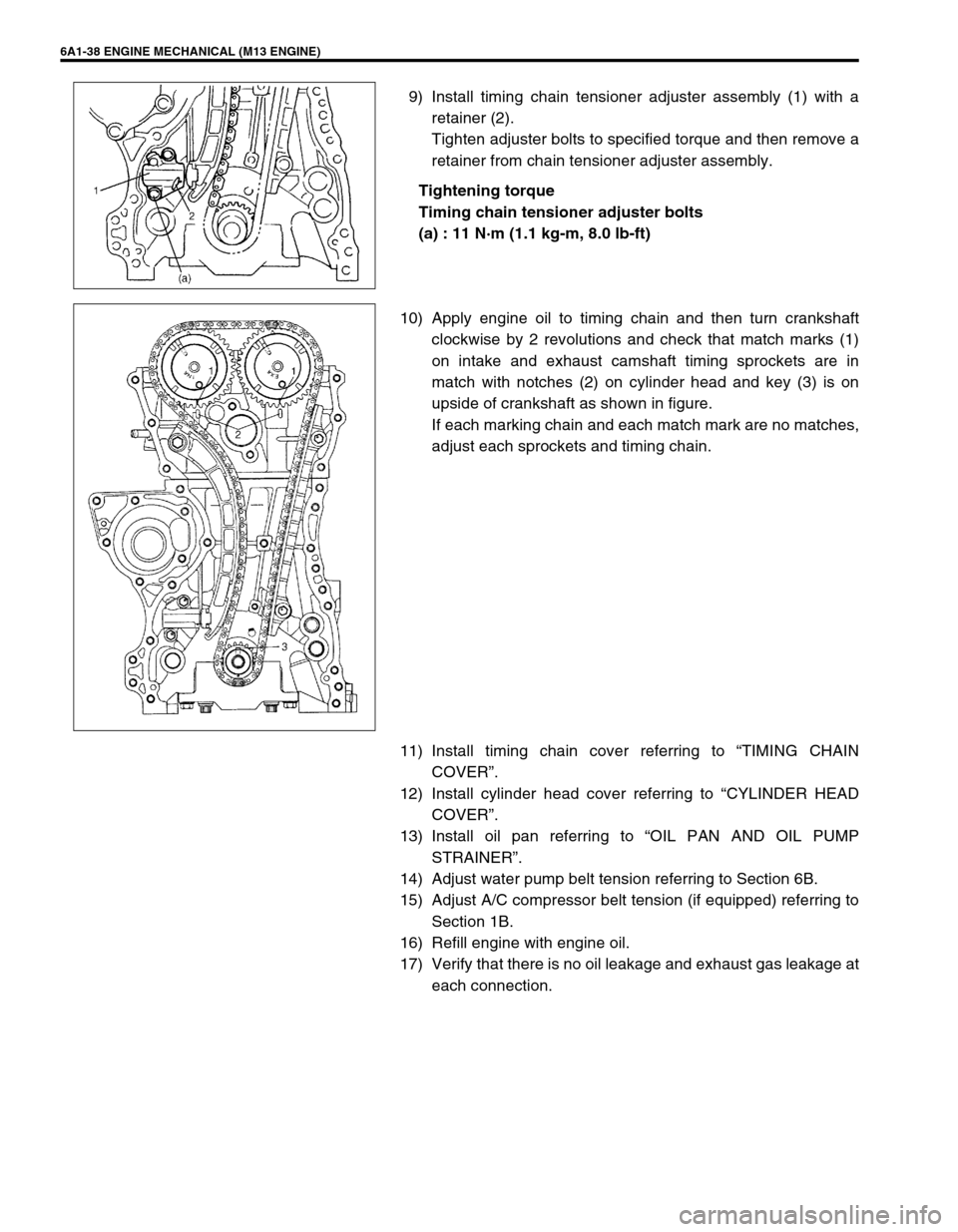
9) Install timing chain tensioner adjuster assembly (1) with a
retainer (2).
Tighten adjuster bolts to specified torque and then remove a
retainer from chain tensioner adjuster assembly.
Tightening torque
Timing chain tensioner adjuster bolts
(a) : 11 N·m (1.1 kg-m, 8.0 lb-ft)
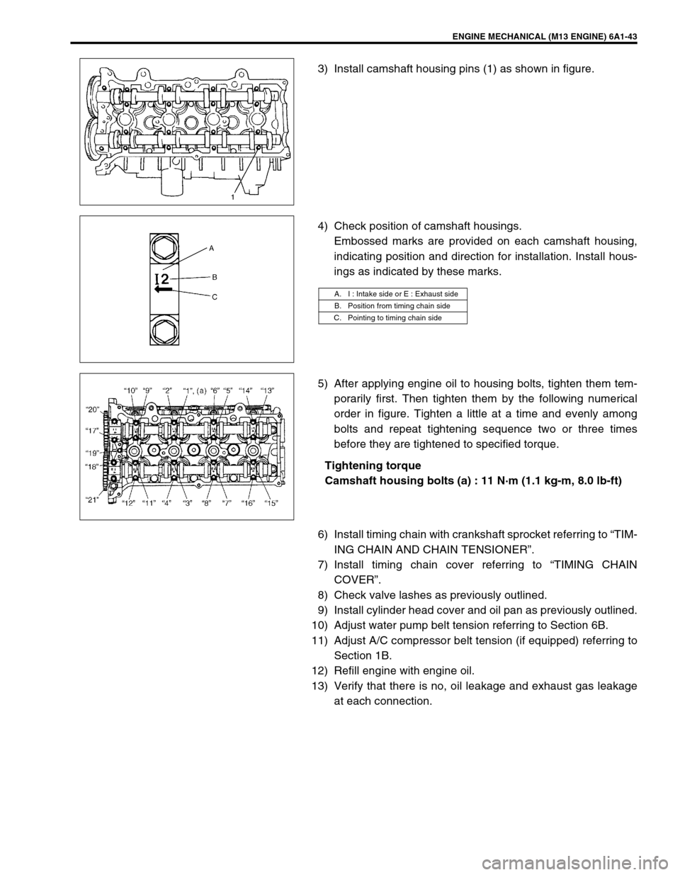
10) Apply engine oil to timing chain and then turn crankshaft
clockwise by 2 revolutions and check that match marks (1)
on intake and exhaust camshaft timing sprockets are in
match with notches (2) on cylinder head and key (3) is on
upside of crankshaft as shown in figure.
If each marking chain and each match mark are no matches,
adjust each sprockets and timing chain.
11) Install timing chain cover referring to “TIMING CHAIN
COVER”.
12) Install cylinder head cover referring to “CYLINDER HEAD
COVER”.
13) Install oil pan referring to “OIL PAN AND OIL PUMP
STRAINER”.
14) Adjust water pump belt tension referring to Section 6B.
15) Adjust A/C compressor belt tension (if equipped) referring to
Section 1B.
16) Refill engine with engine oil.
17) Verify that there is no oil leakage and exhaust gas leakage at
each connection.
Page 544 of 698

ENGINE MECHANICAL (M13 ENGINE) 6A1-43
3) Install camshaft housing pins (1) as shown in figure.
4) Check position of camshaft housings.
Embossed marks are provided on each camshaft housing,
indicating position and direction for installation. Install hous-
ings as indicated by these marks.
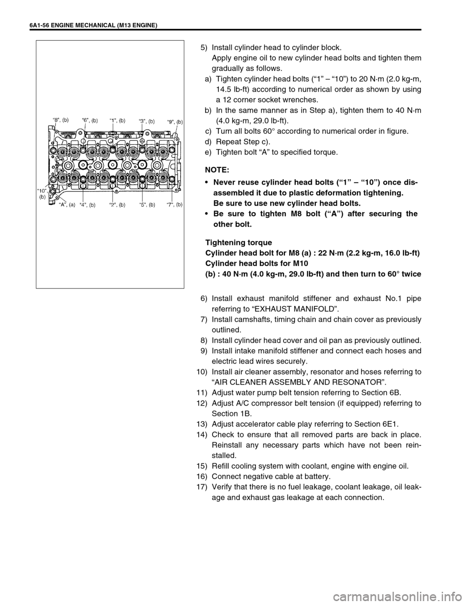
5) After applying engine oil to housing bolts, tighten them tem-
porarily first. Then tighten them by the following numerical
order in figure. Tighten a little at a time and evenly among
bolts and repeat tightening sequence two or three times
before they are tightened to specified torque.
Tightening torque
Camshaft housing bolts (a) : 11 N·m (1.1 kg-m, 8.0 lb-ft)
6) Install timing chain with crankshaft sprocket referring to “TIM-
ING CHAIN AND CHAIN TENSIONER”.
7) Install timing chain cover referring to “TIMING CHAIN
COVER”.
8) Check valve lashes as previously outlined.
9) Install cylinder head cover and oil pan as previously outlined.
10) Adjust water pump belt tension referring to Section 6B.
11) Adjust A/C compressor belt tension (if equipped) referring to
Section 1B.
12) Refill engine with engine oil.
13) Verify that there is no, oil leakage and exhaust gas leakage
at each connection.
A. I : Intake side or E : Exhaust side
B. Position from timing chain side
C. Pointing to timing chain side
Page 557 of 698

6A1-56 ENGINE MECHANICAL (M13 ENGINE)
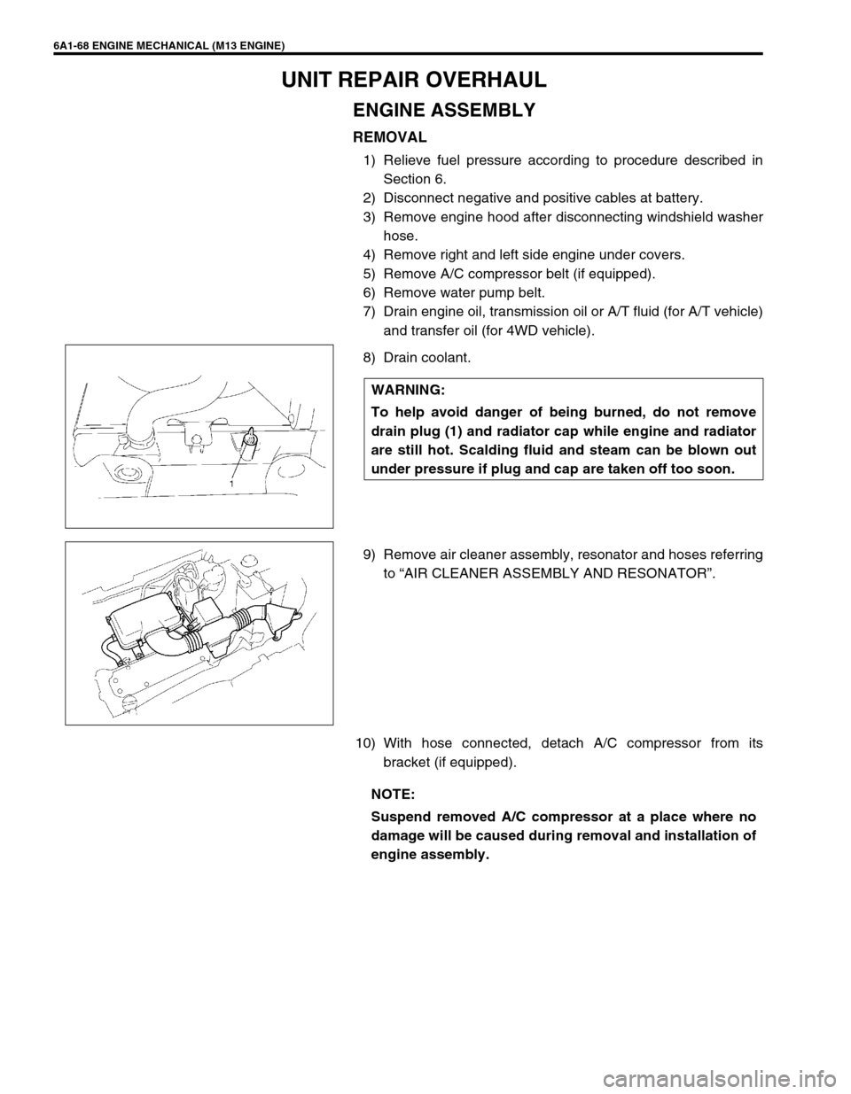
5) Install cylinder head to cylinder block.
Apply engine oil to new cylinder head bolts and tighten them
gradually as follows.
a) Tighten cylinder head bolts (“1” – “10”) to 20 N·m (2.0 kg-m,
14.5 lb-ft) according to numerical order as shown by using
a 12 corner socket wrenches.
b) In the same manner as in Step a), tighten them to 40 N·m
(4.0 kg-m, 29.0 lb-ft).
c) Turn all bolts 60° according to numerical order in figure.
d) Repeat Step c).
e) Tighten bolt “A” to specified torque.
Tightening torque
Cylinder head bolt for M8 (a) : 22 N·m (2.2 kg-m, 16.0 lb-ft)
Cylinder head bolts for M10
(b) : 40 N·m (4.0 kg-m, 29.0 lb-ft) and then turn to 60° twice
6) Install exhaust manifold stiffener and exhaust No.1 pipe
referring to “EXHAUST MANIFOLD”.
7) Install camshafts, timing chain and chain cover as previously
outlined.
8) Install cylinder head cover and oil pan as previously outlined.
9) Install intake manifold stiffener and connect each hoses and
electric lead wires securely.
10) Install air cleaner assembly, resonator and hoses referring to
“AIR CLEANER ASSEMBLY AND RESONATOR”.
11) Adjust water pump belt tension referring to Section 6B.
12) Adjust A/C compressor belt tension (if equipped) referring to
Section 1B.
13) Adjust accelerator cable play referring to Section 6E1.
14) Check to ensure that all removed parts are back in place.
Reinstall any necessary parts which have not been rein-
stalled.
15) Refill cooling system with coolant, engine with engine oil.
16) Connect negative cable at battery.
17) Verify that there is no fuel leakage, coolant leakage, oil leak-
age and exhaust gas leakage at each connection. NOTE:
Never reuse cylinder head bolts (“1” – “10”) once dis-
assembled it due to plastic deformation tightening.
Be sure to use new cylinder head bolts.
Be sure to tighten M8 bolt (“A”) after securing the
other bolt.
Page 567 of 698
6A1-66 ENGINE MECHANICAL (M13 ENGINE)
6) Reverse removal procedure for installation as previously out-
lined.
7) Adjust water pump belt tension referring to Section 6B.
8) Adjust A/C compressor belt tension (if equipped) referring to
Section 1B.
9) Adjust accelerator cable play referring to Section 6E1.
10) Check to ensure that all removed parts are back in place.
Reinstall any necessary parts which have not been rein-
stalled.
11) Refill cooling system with coolant engine with engine oil.
12) Connect negative cable at battery.
13) Verify that there is no fuel leakage, coolant leakage, oil leak-
age and exhaust gas leakage at each connection. NOTE:
Before installing bearing cap, make sure that checking
for connecting rod bolt deformation.
Refer to “INSPECTION” of “CONNECTING ROD”.
Page 569 of 698

6A1-68 ENGINE MECHANICAL (M13 ENGINE)
UNIT REPAIR OVERHAUL
ENGINE ASSEMBLY
REMOVAL
1) Relieve fuel pressure according to procedure described in
Section 6.
2) Disconnect negative and positive cables at battery.
3) Remove engine hood after disconnecting windshield washer
hose.
4) Remove right and left side engine under covers.
5) Remove A/C compressor belt (if equipped).
6) Remove water pump belt.
7) Drain engine oil, transmission oil or A/T fluid (for A/T vehicle)
and transfer oil (for 4WD vehicle).
8) Drain coolant.
9) Remove air cleaner assembly, resonator and hoses referring
to “AIR CLEANER ASSEMBLY AND RESONATOR”.
10) With hose connected, detach A/C compressor from its
bracket (if equipped). WARNING:
To help avoid danger of being burned, do not remove
drain plug (1) and radiator cap while engine and radiator
are still hot. Scalding fluid and steam can be blown out
under pressure if plug and cap are taken off too soon.
NOTE:
Suspend removed A/C compressor at a place where no
damage will be caused during removal and installation of
engine assembly.