Page 415 of 698

6-46 ENGINE GENERAL INFORMATION AND DIAGNOSIS
TABLE A-1 MALFUNCTION INDICATOR LAMP CIRCUIT CHECK - LAMP DOES
NOT COME “ON” AT IGNITION SWITCH ON (BUT ENGINE AT STOP)
WIRING DIAGRAM
CIRCUIT DESCRIPTION
When the ignition switch is turned ON, ECM causes the main relay to turn ON (close the contact point). Then,
ECM being supplied with the main power, turns ON the malfunction indicator lamp (MIL). When the engine
starts to run and no malfunction is detected in the system, MIL goes OFF but if a malfunction was or is detected,
MIL remains ON even when the engine is running.
INSPECTION
1. BATT fuse 3. IG METER fuse 5. Monitor connector 7. To ignition switch
2. Main fuse box 4. To battery 6. MIL
[A] : Case of TYPE A is shown
(See NOTE)[B] : Case of TYPE B is shown
(See NOTE)
1
12V5V
ECM
23
+BB
DA
C
BLK/WHT
BRN/WHT
BLK/RED
BLK/RED
C42 (31P) C41 (24P) G02 (17P)1 2 3 4 5 6 7 8 9
10 11 12 13 14 15 16 17 18 19 20 21
22 23 24 25 26 28 27 29 30 315 6
1 2 3 4 5 6 7
11 12
9 10 11 13 12 14 15 16
16 171 2
7 8
13 14 3 4
9 10
15 17 188
19 20 21 22 23 24
BLK
DN
TS
GNDMON
PPL/WHTC42-27 [A]
C42-16 [A]
PNK/BLUC42-28 [A]
7 4
G02-1 [A]IG1
5
6IG1
WHT/GRN
BLK/WHT
G02-6 [A]
C41-5 C41-6 C41-10 C41-11 [B]C41-14 [B]
C41-15 [B]
C41-8 [B]
G02-9 [B]
PPL/WHT
NOTE:
For TYPE A and TYPE B, refer to NOTE in “ECM VOLTAGE VALUES TABLE” for applicable model.
Step Action Yes No
1 MIL Power Supply Check
1) Turn ignition switch ON.
Do other indicator/warning lights in combination
meter comes ON?Go to Step 2.“IG METER” fuse blown,
main fuse blown, ignition
switch malfunction, “BLK/
WHT” circuit between “IG
METER” fuse and combi-
nation meter or poor cou-
pler connection at
combination meter.
2 ECM Power and Ground Circuit Check
Does engine start?Go to Step 3. Go to TABLE A-5 ECM
POWER AND GROUND
CIRCUIT CHECK.
If engine is not cranked,
go to DIAGNOSIS in Sec-
tion 6G.
Page 418 of 698

ENGINE GENERAL INFORMATION AND DIAGNOSIS 6-49
TABLE A-5 ECM POWER AND GROUND CIRCUIT CHECK - MIL DOESN’T
LIGHT AT IGNITION SWITCH ON AND ENGINE DOESN’T START THOUGH IT IS
CRANKED UP
WIRING DIAGRAM
CIRCUIT DESCRIPTION
When the ignition switch tuned ON, the main relay turns ON (the contact point closes) and the main power is
supplied to ECM.
1. BATT fuse 3. IG METER fuse 5. Monitor connector
2. Main fuse box 4. To battery 6. MIL (if equipped)
[A] : Case of TYPE A is shown (See NOTE) [B] : Case of TYPE B is shown (See NOTE)
1
12V5V
ECM
23
+BB
DA
C
BLK/WHT
BRN/WHT
BLK/RED
BLK/RED
C42 (31P) C41 (24P) G02 (17P)1 2 3 4 5 6 7 8 9
10 11 12 13 14 15 16 17 18 19 20 21
22 23 24 25 26 28 27 29 30 315 6
1 2 3 4 5 6 7
11 12
9 10 11 13 12 14 15 16
16 171 2
7 8
13 14 3 4
9 10
15 17 188
19 20 21 22 23 24
BLK
DN
TS
GNDMON
PPL/WHTC42-27 [A]
C42-16 [A]
PNK/BLUC42-28 [A]
7 4
G02-1 [A]IG1PPL/YEL [A]
5
6IG1
WHT/GRN
BLK/WHT
G02-6 [A]
C41-5 C41-6 C41-10 C41-11 [B]C41-14 [B]
C41-15 [B]
C41-8 [B]
G02-9 [B]PPL/WHT [B]
NOTE:
For TYPE A and TYPE B, refer to NOTE in “ECM VOLTAGE VALUES TABLE” for applicable model.
Page 570 of 698

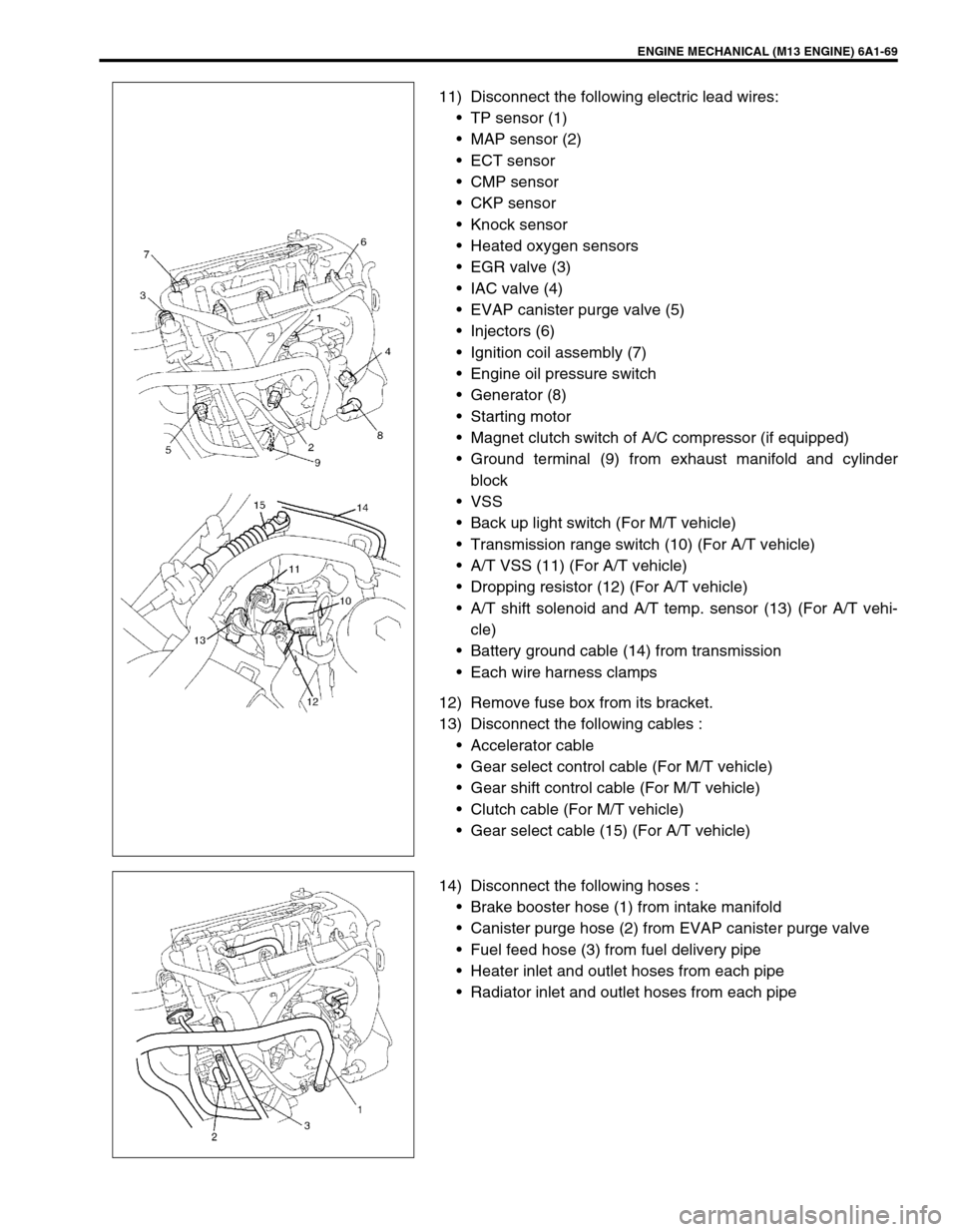
ENGINE MECHANICAL (M13 ENGINE) 6A1-69
11) Disconnect the following electric lead wires:
TP sensor (1)
MAP sensor (2)
ECT sensor
CMP sensor
CKP sensor
Knock sensor
Heated oxygen sensors
EGR valve (3)
IAC valve (4)
EVAP canister purge valve (5)
Injectors (6)
Ignition coil assembly (7)
Engine oil pressure switch
Generator (8)
Starting motor
Magnet clutch switch of A/C compressor (if equipped)
Ground terminal (9) from exhaust manifold and cylinder
block
VSS
Back up light switch (For M/T vehicle)
Transmission range switch (10) (For A/T vehicle)
A/T VSS (11) (For A/T vehicle)
Dropping resistor (12) (For A/T vehicle)
A/T shift solenoid and A/T temp. sensor (13) (For A/T vehi-
cle)
Battery ground cable (14) from transmission
Each wire harness clamps
12) Remove fuse box from its bracket.
13) Disconnect the following cables :
Accelerator cable
Gear select control cable (For M/T vehicle)
Gear shift control cable (For M/T vehicle)
Clutch cable (For M/T vehicle)
Gear select cable (15) (For A/T vehicle)
14) Disconnect the following hoses :
Brake booster hose (1) from intake manifold
Canister purge hose (2) from EVAP canister purge valve
Fuel feed hose (3) from fuel delivery pipe
Heater inlet and outlet hoses from each pipe
Radiator inlet and outlet hoses from each pipe
Page 594 of 698
ENGINE COOLING 6B-5
SYSTEM CIRCUIT
SYSTEM CIRCUIT INSPECTION
Refer to “RADIATOR COOLINGFAN CONTROL SYSTEM CHECK” in Section 6
1. Main fuse box 6. ECM main fuse 11. Radiator and condenser cooling fan motor
2. Generator 7. ECM main relay 12. Refrigerant pressure triple switch (if equipped with A/C)
3. Battery 8. Radiator and condenser cooling fan relay No.1 13. ECT sensor
4. Battery fuse 9. Radiator and condenser cooling fan relay No.2 14. ECM
5. RADTR fuse 10. Radiator and condenser cooling fan relay No.3 15. TO A/C switch
ACG
15A 30A
BLU/WHT
BLK/YEL
BLK
BLU
ORN
BLK
BLK
BLUH–
H+
L– L+
GRN/BLK
BLU/BLK
BRN/WHT
YEL/GRN
PNK/GRN
PPL/YEL
LT GRN/BLK
BLK/RED
BLK/RED 80A
145
6
2
3
7
8
9
11
10
13 15
12
14
Page:
< prev 1-8 9-16 17-24