2000 SUZUKI SWIFT fuse
[x] Cancel search: fusePage 162 of 698

ELECTRICAL POWER STEERING (P/S) SYSTEM 3B1-21
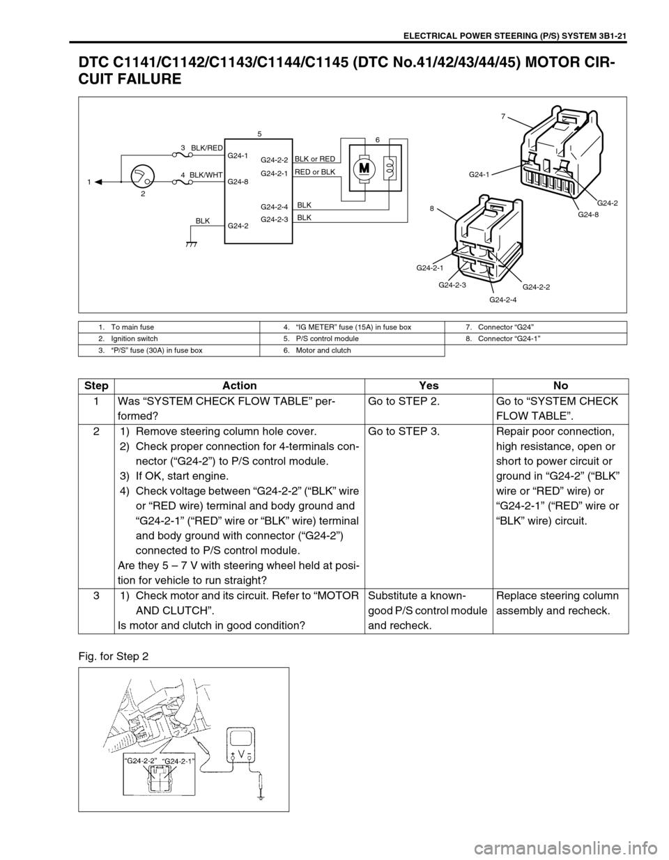
DTC C1141/C1142/C1143/C1144/C1145 (DTC No.41/42/43/44/45) MOTOR CIR-
CUIT FAILURE
Fig. for Step 2
1. To main fuse 4.“IG METER” fuse (15A) in fuse box 7. Connector “G24”
2. Ignition switch 5. P/S control module 8. Connector “G24-1”
3.“P/S” fuse (30A) in fuse box 6. Motor and clutch
MG24-1
G24-8G24-2
7
G24-2-2
G24-2-4 G24-2-3 G24-2-1
8
G24-2 G24-1
G24-8G24-2-2
G24-2-1
G24-2-4
G24-2-3 1
23
46 5
BLK/WHTBLK/RED
BLKBLK BLK RED or BLK BLK or RED
Step Action Yes No
1Was “SYSTEM CHECK FLOW TABLE” per-
formed?Go to STEP 2. Go to “SYSTEM CHECK
FLOW TABLE”.
2 1) Remove steering column hole cover.
2) Check proper connection for 4-terminals con-
nector (“G24-2”) to P/S control module.
3) If OK, start engine.
4) Check voltage between “G24-2-2” (“BLK” wire
or “RED wire) terminal and body ground and
“G24-2-1” (“RED” wire or “BLK” wire) terminal
and body ground with connector (“G24-2”)
connected to P/S control module.
Are they 5 – 7 V with steering wheel held at posi-
tion for vehicle to run straight?Go to STEP 3. Repair poor connection,
high resistance, open or
short to power circuit or
ground in “G24-2” (“BLK”
wire or “RED” wire) or
“G24-2-1” (“RED” wire or
“BLK” wire) circuit.
3 1) Check motor and its circuit. Refer to “MOTOR
AND CLUTCH”.
Is motor and clutch in good condition?Substitute a known-
good P/S control module
and recheck.Replace steering column
assembly and recheck.
Page 163 of 698

3B1-22 ELECTRICAL POWER STEERING (P/S) SYSTEM
DTC C1151 (DTC No.51) CLUTCH CIRCUIT FAILURE
1. To main fuse 4.“IG METER” fuse (15A) in fuse box 7. Connector “G24”
2. Ignition switch 5. P/S control module 8. Connector “G24-2”
3.“P/S” fuse (30A) in fuse box 6. Motor and clutch
M
G24-2 G24-1
G24-8G24-2-2
G24-2-1
G24-2-4
G24-2-3 1
23
46 5
BLK/WHTBLK/RED
BLKBLK BLK RED or BLKBLK or RED
G24-1
G24-8G24-2
7
G24-2-2
G24-2-4 G24-2-3 G24-2-1
8
Step Action Yes No
1Was “SYSTEM CHECK FLOW TABLE” per-
formed?Go to STEP 2. Go to “SYSTEM CHECK
FLOW TABLE”.
2 1) Remove steering column lower cover.
2) Check proper connection for 4-terminals
connector (“G24-2”) to P/S control module.
3) If OK, start engine.
4) Check voltage between “G24-2-4” (“BLK”
wire) terminal and body ground with con-
nector (“G24-2”) connected to P/S control
module.
Is it 0 V?Go to STEP 3. Repair poor connection,
high resistance, open or
short to power circuit or
ground in “G24-2-4”
(“BLK” wire) circuit.
3 1) Check voltage between “G24-2-3” (“BLK”
wire) terminal and body ground with con-
nector (“G24-2”) connected to P/S control
module.
Is it 10 – 14 V with steering wheel held at posi-
tion for vehicle to run straight?Go to STEP 4. Repair poor connection,
high resistance, open or
short to power circuit or
ground in “G24-2-3”
(“BLK” wire) circuit.
4 1) Check motor and its circuit. Refer to
“MOTOR AND CLUTCH”.
Is motor and clutch in good condition?Substitute a known-good
P/S control module and
recheck.Replace steering column
assembly and recheck.
Page 165 of 698

3B1-24 ELECTRICAL POWER STEERING (P/S) SYSTEM
DTC C1153(DTC No.53) P/S CONTROL MODULE POWER SUPPLY CIRCUIT
FAILURE
Fig. for Step 2
DTC C1152/C1154/C1155 (DTC No.52/54/55) P/S CONTROL MODULE FAILURE
Substitute a known-good P/S control module and recheck.
1. To main fuse 3.“P/S” fuse (30A) in fuse box 5. P/S control module
2. Ignition switch 4.“IG METER” fuse (15A) in fuse box 6. Connector “G24”
G24-2 G24-1
G24-8 13
45
BLK/WHT BLK/RED
BLK
G24-1
G24-8G24-2
6
Step Action Yes No
1Was “SYSTEM CHECK FLOW TABLE” per-
formed?Go to STEP 2. Go to “SYSTEM CHECK
FLOW TABLE”.
2 1) Remove steering column lower cover.
2) Check “P/S” fuse and proper connection to
P/S control module at “G24-1” (“BLK/WHT”
wire) terminal.
3) If OK, check voltage between “G24-1” termi-
nal and body ground with connector (“G24”)
connected to P/S control module.
Is it 10 – 14 V?Check intermittent trou-
ble. Refer to “INTERMIT-
TENT TROUBLE” in
SECTION 0A.
If OK, substitute a known-
good P/S control module
and recheck.Repair poor connection or
high resistance in “G24-1”
(“BLK/RED” wire) circuit.
Page 332 of 698

ANTILOCK BRAKE SYSTEM (ABS) 5E-7
1. Battery 9. ABS hydraulic unit/control module assembly 17. Left-rear wheel speed sensor
2. Main fuses 10. Terminal arrangement of connector E19 for ABS
hydraulic unit/control module assembly18. Right-front wheel speed sensor
3. Ignition switch 11. ABS fail-safe relay (Solenoid valve relay) 19. Left-front wheel speed sensor
4. Circuit fuses 12. ABS pump motor relay 20. Data link connector
5. Combination meter 13. Pump motor 21. To ECM, SDM and EPS controller (if equipped)
6. ABS warning lamp 14. Solenoid valves 22. Stop lamp
7. Brake warning lamp (“EBD” warning lamp) 15. Diagnosis monitor coupler 23. Stop lamp switch
8. Warning lamp driver module (for ABS) 16. Right-rear wheel speed sensor 24. G sensor (For 4WD vehicle only)
Wire color
BLK : Black LT GRN/BLK : Light Green/Black RED/BLU : Red/Blue
BLK/ORN : Black/Orange LT GRN/RED : Light Green/Red WHT : White
BLK/YEL : Black/Yellow ORN : Orange WHT/BLK : White/Black
BLU : Blue PNK : Pink WHT/BLU : White/Blue
BRN : Brown PNK/BLU Pink/Blue WHT/RED : White/Red
GRN : Green RED : Red YEL : Yellow
GRN/ORN : Green/Orange RED/BLK : Red/Black
TERMINAL CIRCUIT
E191–
2 Stop lamp switch
3 Right-front wheel speed sensor (+)
4 Right-front wheel speed sensor (–)
5–
6 Right-rear wheel speed sensor (–)
7 Right-rear wheel speed sensor (+)
8–
9–
10 Brake warning lamp (EBD warning lamp)
11 G sensor (For 4WD vehicle only)
12 Diagnosis switch terminal
13 Ground (For G sensor) (For 4WD vehicle only)
14 ABS warning lamp
15 Left-front wheel speed sensor (+)
16 Left-front wheel speed sensor (–)
17–
18 Ignition switch
19 Left-rear wheel speed sensor (+)
20 Left-rear wheel speed sensor (–)
21 Data link connector
22 Ground (for ABS pump motor)
23 ABS pump motor relay
24 Ground (for ABS control module)
25 ABS fail-safe relay
Page 338 of 698

ANTILOCK BRAKE SYSTEM (ABS) 5E-13
TABLE – A ABS WARNING LAMP CIRCUIT CHECK – LAMP DOES NOT COME
“ON” AT IGNITION SWITCH ON
CIRCUIT DESCRIPTION
Operation (ON/OFF) of ABS warning lamp is controlled by ABS control module through lamp driver module in
combination meter.
If the Antilock brake system is in good condition, ABS control module turns ABS warning lamp ON at the ignition
switch ON, keeps it ON for 2 seconds and then turns it OFF. If an abnormality in the system is detected, ABS
warning lamp is turned ON continuously by ABS control module. Also, it is turned ON continuously by lamp
driver module when the connector of ABS control module is disconnected.
INSPECTION
1. Main fuse 5. ABS warning lamp 9. Brake fluid level switch
2. Ignition switch 6. Brake warning lamp 10. ABS hydraulic unit/control module assembly
3. Circuit fuse 7. Lamp driver module 11. ABS hydraulic unit/control module connector
4. Combination meter 8. Parking brake switch
Step Action Yes No
1 1) Turn ignition switch ON.
Do other warning lamp come ON?Go to Step 2. Go to Step 4.
2 1) Disconnect ABS hydraulic unit/control mod-
ule connector.
Does ABS warning lamp light with ignition
switch ON?Substitute a known-good ABS
hydraulic unit/control module
assembly and recheck.Go to Step 3.
3 1) Remove combination meter.
Is bulb of ABS warning lamp in good condition?“RED/BLU” circuit shorted to
ground. If OK, replace combina-
tion meter (lamp driver module).Replace bulb.
4 Is IG fuse in good condition? Open in “BLK/WHT” wire to
combination meter or poor con-
nection.Repair and replace.
Page 352 of 698

ANTILOCK BRAKE SYSTEM (ABS) 5E-27
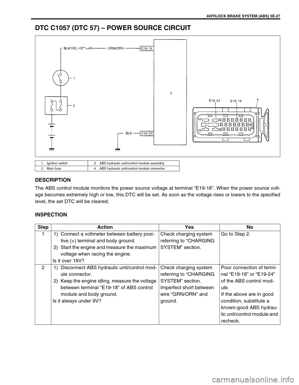
DTC C1057 (DTC 57) – POWER SOURCE CIRCUIT
DESCRIPTION
The ABS control module monitors the power source voltage at terminal “E19-18”. When the power source volt-
age becomes extremely high or low, this DTC will be set. As soon as the voltage rises or lowers to the specified
level, the set DTC will be cleared.
INSPECTION
1. Ignition switch 3. ABS hydraulic unit/control module assembly
2. Main fuse 4. ABS hydraulic unit/control module connector
Step Action Yes No
1 1) Connect a voltmeter between battery posi-
tive (+) terminal and body ground.
2) Start the engine and measure the maximum
voltage when racing the engine.
Is it over 18V?Check charging system
referring to “CHARGING
SYSTEM” section.Go to Step 2.
2 1) Disconnect ABS hydraulic unit/control mod-
ule connector.
2) Keep the engine idling, measure the voltage
between terminal “E19-18” of ABS control
module and body ground.
Is it always under 9V?Check charging system
referring to “CHARGING
SYSTEM” section.
Imperfect short between
wire “GRN/ORN” and
ground.Poor connection of termi-
nal “E19-18” or “E19-24”
of the ABS control mod-
ule.
If the above are in good
condition, substitute a
known-good ABS hydrau-
lic unit/control module and
recheck.
Page 354 of 698

ANTILOCK BRAKE SYSTEM (ABS) 5E-29
DTC C1063 (DTC 63) – ABS FAIL-SAFE RELAY CIRCUIT
DESCRIPTION
ABS control module monitors the voltage at the terminal of solenoid circuit constantly with ignition switch turned
ON. Also, immediately after ignition switch is turned ON, perform initial check as follows.
Switch fail-safe relay in the order of OFF → ON and check if voltage changes to Low → High. If anything faulty
is found in the initial check and when the voltage is low with ignition switch turned ON, this DTC will be set.
INSPECTION
1. Ignition switch 3. ABS hydraulic unit/control module connector 5. To pump motor relay
2. ABS hydraulic unit/control module assembly 4. To solenoid valves 6. Fail-safe relay
Step Action Yes No
1 Check battery voltage. Is it about 11 V or
higher?Go to Step 2. Check charging system
referring to “CHARGING
SYSTEM” section.
2 Check ABS main fuse and connection.
Is it in good condition?Go to Step 3. Repair and/or replace
fuse.
3 1) Ignition switch OFF.
2) Disconnect ABS hydraulic unit/control mod-
ule connector.
3) Check proper connection to ABS hydraulic
unit/control module at terminal “E19-25”.
4) If OK, then measure voltage between con-
nector terminal “E19-25” and body ground.
Is it 10 – 14 V?Substitute a known-good
ABS hydraulic unit/con-
trol module assembly and
recheck.“WHT/BLU” circuit open
or short to ground.
Page 368 of 698

ANTILOCK BRAKE SYSTEM (ABS) 5E-43
G SENSOR (FOR 4WD VEHICLE ONLY)
REMOVAL
1) Turn ignition switch OFF and disconnect battery negative
cable.
2) Remove ABS fuse from fuse box.
3) Disconnect ABS hydraulic unit/control module assembly
connector by pulling up lock.
4) Remove center console box.
5) Remove G sensor (1) from floor.
6) Disconnect connector from sensor.
INSPECTION
Connect positive cable of 12 volt battery to “A” terminal of sensor
and ground cable to “C” terminal. Then using voltmeter, check
voltage between “B” terminal and “C” terminal.
G sensor specification
When placed horizontally : 2 – 3 V
When placed upright with arrow upward : 3 – 4 V
When placed upright with arrow downward : 1 – 2 V
If measured voltage is not as specified, replace sensor.
INSTALLATION
1) Connect connector to sensor securely.
2) Install sensor onto floor so that arrow mark directs vehicle
forward.
3) Connect ABS hydraulic unit/control module assembly con-
nector.
4) Install ABS fuse to fuse box.
5) Install rear console box.CAUTION:
Sensor must not be dropped or shocked. It will affect its
original performance.
2. Label1
2
[A] : Horizontal
[B] : Upright with arrow upward
[C] : Upright with arrow downward