Page 151 of 698
3B1-10 ELECTRICAL POWER STEERING (P/S) SYSTEM
SERIAL DATA LINK CIRCUIT CHECK
DIAGNOSTIC FLOW TABLE
CAUTION:
Be sure to perform “SYSTEM CHECK FLOW TABLE” before starting diagnosis according to flow table.
1. Main fuse box 6. Combination meter 11. Data link connector (DLC)
2.“EPS” fuse (30 A) 7. Speedometer 12. To ECM, SDM and ABS hydraulic unit/control module
assembly (if equipped)
3. Ignition switch 8.“EPS” warning lamp 13. P/S control module
4. Circuit fuse box 9. To vehicle speed sensor (VSS) 14. Connector “G24”
5.“IG coil” fuse (15 A) 10. To main fuse box
Step Action Yes No
1Was “SYSTEM CHECK FLOW TABLE” per-
formed?Go to Step 2. Go to “SYSTEM CHECK
FLOW TABLE” in this sec-
tion.
2 1) Make sure that SUZUKI scan tool free from
malfunction and correct cartridge for P/S
system is used.
2) Turn ignition switch to OFF position.
3) Check proper connection of SUZUKI scan
tool to DLC.
Is connection in good condition?Go to Step 3. Properly connect SUZUKI
scan tool to DLC.
Page 154 of 698
ELECTRICAL POWER STEERING (P/S) SYSTEM 3B1-13
TABLE A - MALFUNCTION INDICATOR LAMP DOES NOT COME ON AT IGNI-
TION SWITCH ON BUT LEAVING ENGINE OFF
CIRCUIT
1. To main fuse 5.“EPS” warning lamp 9. Ground terminal
2. Ignition switch 6. Combination meter 10. P/S control module
3.“P/S” fuse (30A) in fuse box 7. Monitor coupler 11. Connector “G24”
4.“IG METER” fuse (15A) in fuse box 8. Diagnosis switch terminal
G24-1
G24-8
G24-5
G24-4
G24-2 1
23
4
5 6
7
8
910
BLK/WHT
BLK/WHTBLK/RED
YEL
PPL/WHT
BLKBLK
87 7
6
G24-1
G24-4
G24-5
G24-8G24-2
11
Page 155 of 698

3B1-14 ELECTRICAL POWER STEERING (P/S) SYSTEM
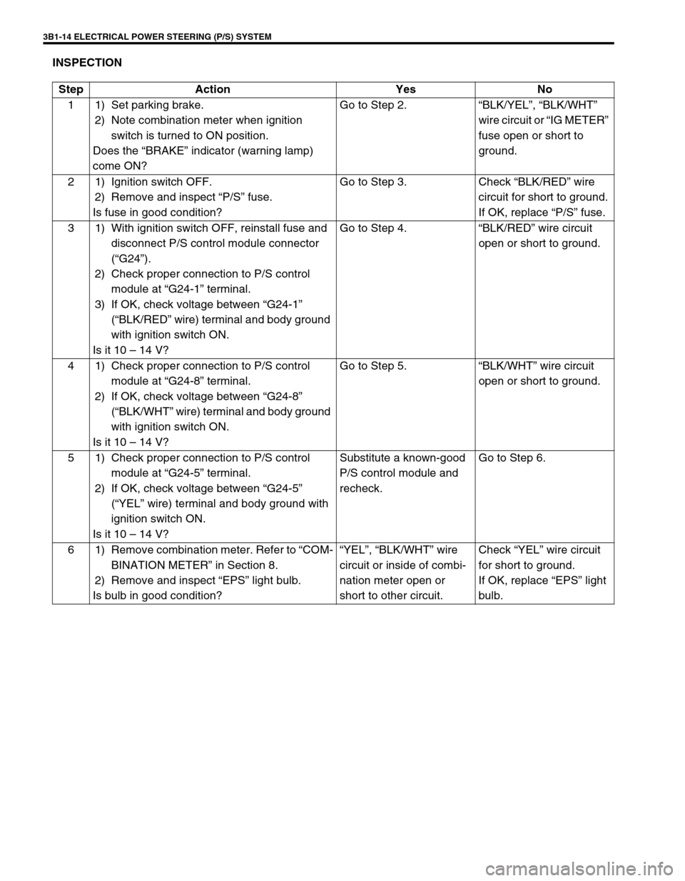
INSPECTION
Step Action Yes No
1 1) Set parking brake.
2) Note combination meter when ignition
switch is turned to ON position.
Does the “BRAKE” indicator (warning lamp)
come ON?Go to Step 2.“BLK/YEL”, “BLK/WHT”
wire circuit or “IG METER”
fuse open or short to
ground.
2 1) Ignition switch OFF.
2) Remove and inspect “P/S” fuse.
Is fuse in good condition?Go to Step 3. Check “BLK/RED” wire
circuit for short to ground.
If OK, replace “P/S” fuse.
3 1) With ignition switch OFF, reinstall fuse and
disconnect P/S control module connector
(“G24”).
2) Check proper connection to P/S control
module at “G24-1” terminal.
3) If OK, check voltage between “G24-1”
(“BLK/RED” wire) terminal and body ground
with ignition switch ON.
Is it 10 – 14 V?Go to Step 4.“BLK/RED” wire circuit
open or short to ground.
4 1) Check proper connection to P/S control
module at “G24-8” terminal.
2) If OK, check voltage between “G24-8”
(“BLK/WHT” wire) terminal and body ground
with ignition switch ON.
Is it 10 – 14 V?Go to Step 5.“BLK/WHT” wire circuit
open or short to ground.
5 1) Check proper connection to P/S control
module at “G24-5” terminal.
2) If OK, check voltage between “G24-5”
(“YEL” wire) terminal and body ground with
ignition switch ON.
Is it 10 – 14 V?Substitute a known-good
P/S control module and
recheck.Go to Step 6.
6 1) Remove combination meter. Refer to “COM-
BINATION METER” in Section 8.
2) Remove and inspect “EPS” light bulb.
Is bulb in good condition?“YEL”, “BLK/WHT” wire
circuit or inside of combi-
nation meter open or
short to other circuit.Check “YEL” wire circuit
for short to ground.
If OK, replace “EPS” light
bulb.
Page 157 of 698

3B1-16 ELECTRICAL POWER STEERING (P/S) SYSTEM
DTC C1111 (DTC No.11) TORQUE SENSOR MAIN CIRCUIT FAILURE
DTC C1113 (DTC No.13) TORQUE SENSOR MAIN AND SUB CIRCUIT FAILURE
DTC C1115 (DTC No.15) TORQUE SENSOR SUB CIRCUIT FAILURE
1. To main fuse 4.“IG METER” fuse (15A) in fuse box 7. Connector “G24”
2. Ignition switch 5. P/S control module 8. Connector “G24-1”
3.“P/S” fuse (30A) in fuse box 6. Torque sensor
G24-2 G24-1
G24-8G24-1-4 G24-1-3
G24-1-5G24-1-2G24-1-1
1
23
45
6
BLK/WHT BLK/RED
BLK WHTYEL BLK BLU RED
G24-1
G24-8G24-2
7
G24-1-5
G24-1-4 G24-1-3 G24-1-2 G24-1-18
Step Action Yes No
11)Was “SYSTEM CHECK FLOW TABLE” per-
formed?Go to STEP 2. Go to “SYSTEM CHECK
FLOW TABLE”.
2 1) Is DTC C1114 (DTC No.14) or C1116 (DTC
No.16) indicated, too?Go to flow table corre-
sponding to each DTC
No.Go to STEP 3.
3 1) Check proper connection for 5-terminals
connector (“G24-1”) to P/S control module.
2) If OK, check torque sensor and its circuit.
Refer to “TORQUE SENSOR”.
Is torque sensor in good condition?Substitute a known-good
P/S control module and
recheck.Replace steering column
assembly and recheck.
Page 158 of 698

ELECTRICAL POWER STEERING (P/S) SYSTEM 3B1-17
DTC C1114 (DTC No.14) TORQUE SENSOR 5V POWER SUPPLY CIRCUIT FAIL-
URE
Fig. for Step 2
1. To main fuse 4.“IG METER” fuse (15A) in fuse box 7. Connector “G24”
2. Ignition switch 5. P/S control module 8. Connector “G24-1”
3.“P/S” fuse (30A) in fuse box 6. Torque sensor
G24-1
G24-8G24-2
7
G24-1-5
G24-1-4 G24-1-3 G24-1-2 G24-1-18
G24-2 G24-1
G24-8G24-1-4G24-1-3
G24-1-5G24-1-2G24-1-1
1
23
45
6
BLK/WHT BLK/RED
BLK WHTYEL BLK BLU RED
Step Action Yes No
1Was “SYSTEM CHECK FLOW TABLE” per-
formed?Go to STEP 2. Go to “SYSTEM CHECK
FLOW TABLE”.
2 1) Remove steering column hole cover.
2) Check proper connection for 5-terminals
connector (“G24-1”) to P/S control module.
3) If OK, turn ignition switch ON.
4) Check voltage between “G24-1-2” (“BLU”
wire) terminal of 5-terminals connector
(“G24-1”) and body ground with connector
(“G24-1”) connected to P/S control module.
Is it about 5 V?Go to STEP 3. Repair high resistance,
open or short to power cir-
cuit or ground in 5V power
supply (“BLU” wire) cir-
cuit.
3 1) Check torque sensor and its circuit. Refer to
“TORQUE SENSOR”.
Is torque sensor in good condition?Substitute a known-good
P/S control module and
recheck.Replace steering column
assembly and recheck.
Page 159 of 698

3B1-18 ELECTRICAL POWER STEERING (P/S) SYSTEM
DTC C1116 (DTC No.16) TORQUE SENSOR 8V POWER SUPPLY CIRCUIT FAIL-
URE
Fig. for Step 2
1. To main fuse 4.“IG METER” fuse (15A) in fuse box 7. Connector “G24”
2. Ignition switch 5. P/S control module 8. Connector “G24-1”
3.“P/S” fuse (30A) in fuse box 6. Torque sensor
G24-1
G24-8G24-2
7
G24-1-5
G24-1-4 G24-1-3 G24-1-2 G24-1-18
G24-2 G24-1
G24-8G24-1-4 G24-1-3
G24-1-5 G24-1-2 G24-1-1
1
23
45
6
BLK/WHTBLK/RED
BLK WHTYEL BLK BLU RED
Step Action Yes No
1Was “SYSTEM CHECK FLOW TABLE” per-
formed?Go to STEP 2. Go to “SYSTEM CHECK
FLOW TABLE”.
2 1) Remove steering column hole cover.
2) Check proper connection for 5-terminals
connector (“G24-1”) to P/S control module.
3) If OK, turn ignition switch ON.
4) Measure voltage between “G24-1-1” (“RED”
wire) terminal of 5-terminals connector
(“G24-1”) and body ground with connector
(“G24-1”) connected to P/S control module.
Is it about 8 V?Go to STEP 3. Repair high resistance,
open or short to power cir-
cuit or ground in 8V power
supply (“RED” wire) cir-
cuit.
3 1) Check torque sensor and its circuit. Refer to
“TORQUE SENSOR”.
Is torque sensor in good condition?Substitute a known-good
P/S control module and
recheck.Replace steering column
assembly and recheck.
Page 160 of 698

ELECTRICAL POWER STEERING (P/S) SYSTEM 3B1-19
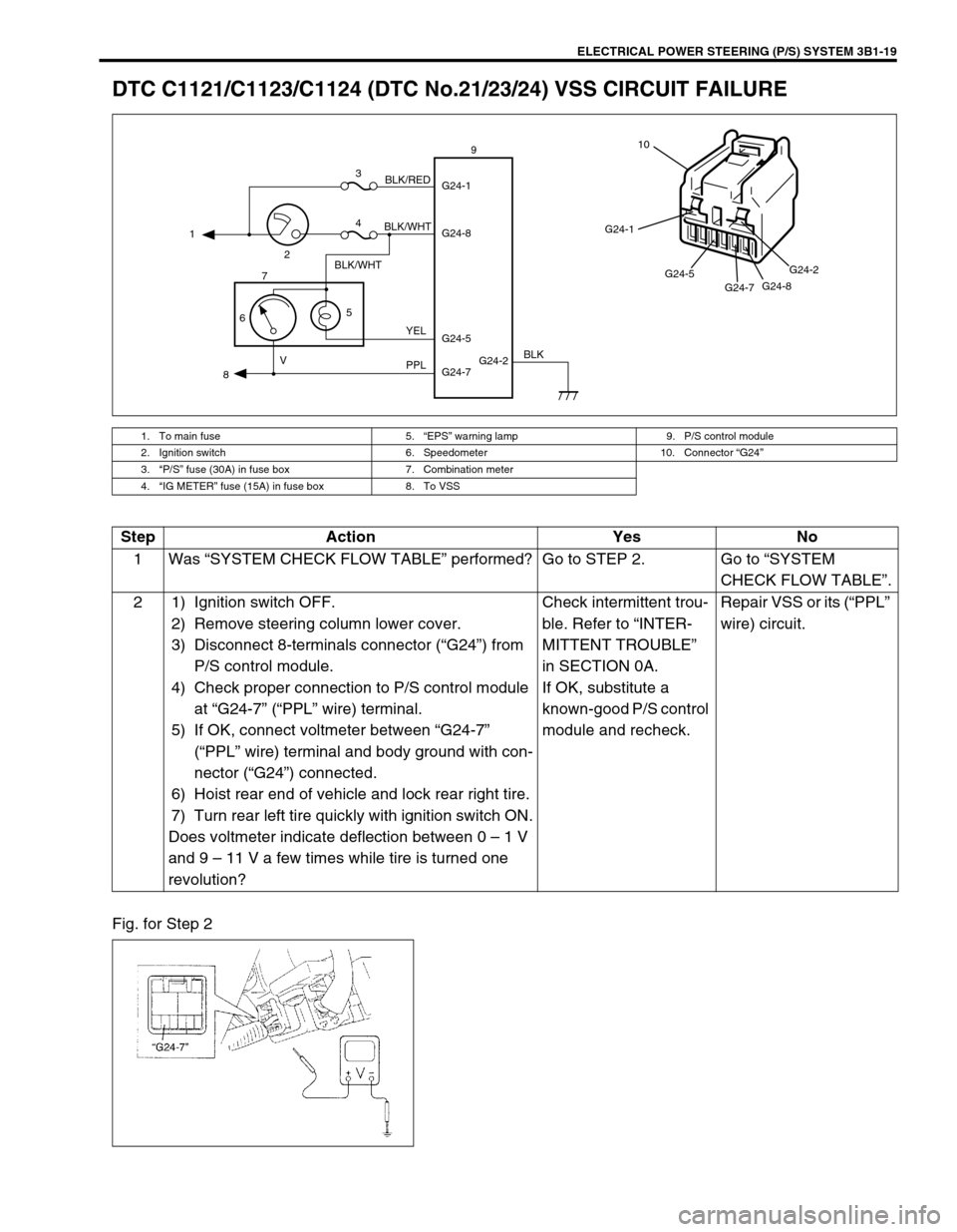
DTC C1121/C1123/C1124 (DTC No.21/23/24) VSS CIRCUIT FAILURE
Fig. for Step 2
1. To main fuse 5.“EPS” warning lamp 9. P/S control module
2. Ignition switch 6. Speedometer 10. Connector “G24”
3.“P/S” fuse (30A) in fuse box 7. Combination meter
4.“IG METER” fuse (15A) in fuse box 8. To VSS
G24-2 G24-1
G24-8
G24-7 G24-5 1
23
4
5
67
89
BLK/WHT
BLK/WHTBLK/RED
YEL
PPL VBLK
G24-1
G24-5
G24-7G24-8G24-2
10
Step Action Yes No
1Was “SYSTEM CHECK FLOW TABLE” performed? Go to STEP 2. Go to “SYSTEM
CHECK FLOW TABLE”.
2 1) Ignition switch OFF.
2) Remove steering column lower cover.
3) Disconnect 8-terminals connector (“G24”) from
P/S control module.
4) Check proper connection to P/S control module
at “G24-7” (“PPL” wire) terminal.
5) If OK, connect voltmeter between “G24-7”
(“PPL” wire) terminal and body ground with con-
nector (“G24”) connected.
6) Hoist rear end of vehicle and lock rear right tire.
7) Turn rear left tire quickly with ignition switch ON.
Does voltmeter indicate deflection between 0 – 1 V
and 9 – 11 V a few times while tire is turned one
revolution?Check intermittent trou-
ble. Refer to “INTER-
MITTENT TROUBLE”
in SECTION 0A.
If OK, substitute a
known-good P/S control
module and recheck.Repair VSS or its (“PPL”
wire) circuit.
Page 161 of 698

3B1-20 ELECTRICAL POWER STEERING (P/S) SYSTEM
DTC C1122 (DTC No.22) ENGINE SPEED SIGNAL CIRCUIT FAILURE
1. To main fuse 4.“IG METER” fuse (15A) in fuse box 7. Connector “G24”
2. Ignition switch 5. ECM
3.“P/S” fuse (30A) in fuse box 6. P/S control module
G24-2 G24-1
G24-8
G24-6 1
23
4
56
BLK/WHT BLK/RED
BRNBLK
G24-1
G24-6
G24-8G24-2
7
Step Action Yes No
1Was “SYSTEM CHECK FLOW TABLE” per-
formed?Go to STEP 2. Go to “SYSTEM CHECK
FLOW TABLE”.
2 1) Recheck DTC with engine running.
Is DTC C1122 (DTC No.22) indicated?Go to STEP 3. It is nothing abnormal for
DTC C1122 (DTC No.22).
P/S system is in normal
condition.
3 1) Check proper connection to P/S control mod-
ule and ECM at each “BRN” wire terminal (P/
S control module side: “G24-6” terminal, ECM
side : Refer to in SECTION 6E), then check
intermittent trouble. Refer to “INTERMITTENT
TROUBLE” in SECTION 0A.
2) If they are OK, check high resistance, open or
short to power circuit or ground in “BRN” wire
circuit.
Is check result in good condition?Substitute a known-
good P/S control mod-
ule and recheck.Repair.