Page 99 of 698

1B-34 AIR CONDITIONING (OPTIONAL)
A/C EVAPORATOR TEMPERATURE SENSOR
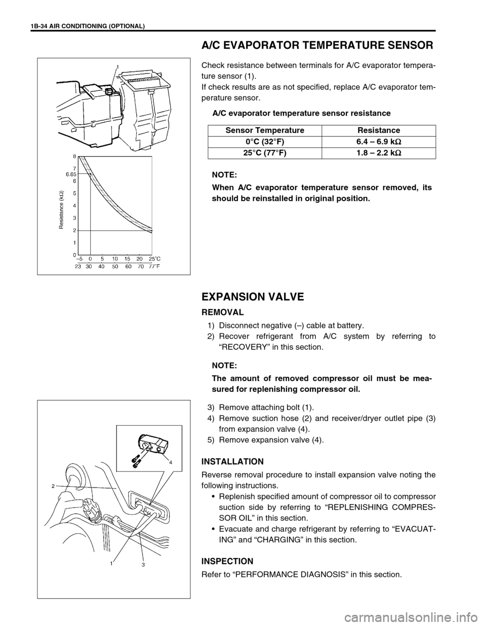
Check resistance between terminals for A/C evaporator tempera-
ture sensor (1).
If check results are as not specified, replace A/C evaporator tem-
perature sensor.
A/C evaporator temperature sensor resistance
EXPANSION VALVE
REMOVAL
1) Disconnect negative (–) cable at battery.
2) Recover refrigerant from A/C system by referring to
“RECOVERY” in this section.
3) Remove attaching bolt (1).
4) Remove suction hose (2) and receiver/dryer outlet pipe (3)
from expansion valve (4).
5) Remove expansion valve (4).
INSTALLATION
Reverse removal procedure to install expansion valve noting the
following instructions.
Replenish specified amount of compressor oil to compressor
suction side by referring to “REPLENISHING COMPRES-
SOR OIL” in this section.
Evacuate and charge refrigerant by referring to “EVACUAT-
ING” and “CHARGING” in this section.
INSPECTION
Refer to “PERFORMANCE DIAGNOSIS” in this section. Sensor Temperature Resistance
0°C (32°F) 6.4 – 6.9 k
Ω
ΩΩ Ω
25°C (77°F) 1.8 – 2.2 k
Ω
ΩΩ Ω
NOTE:
When A/C evaporator temperature sensor removed, its
should be reinstalled in original position.
NOTE:
The amount of removed compressor oil must be mea-
sured for replenishing compressor oil.
Page 101 of 698
1B-36 AIR CONDITIONING (OPTIONAL)
A/C SWITCH
REMOVAL AND INSTALLATION
Refer to “HEATER CONTROL ASSEMBLY” in Section 1A.
INSPECTION
Press A/C switch button and check if there is continuity
between terminals “A” and “B”.
Connect battery voltage (+) to terminal “C” and (–) to termi-
nal “A”, and then press A/C Switch button and check if indi-
cator lamp lights.
RADIATOR/CONDENSER COOLING FAN
MOTOR RELAY No.1, No.2 and No.3
INSPECTION
Refer to “RADIATOR FAN RELAY” in Section 6B.
COMPRESSOR
REMOVAL
1) Run engine at idle speed with air conditioning ON for 10 min-
utes. After that stop the engine.
2) Disconnect negative (–) cable at battery.
3) Recover refrigerant from refrigeration system by referring to
“RECOVERY” in this section.
4) Remove front bumper by referring to “FRONT BUMPER” in
Section 8.
5) Remove engine food cover (1) from vehicle body.
NOTE:
The amount of removed compressor oil must be mea-
sured for replenishing compressor oil.
Page 103 of 698
1B-38 AIR CONDITIONING (OPTIONAL)
MAGNET CLUTCH
INSPECTION
Check clutch plate and clutch pulley for wear and oil soaked
conditions respectively.
Check clutch pulley bearing for noise, wear and grease leak-
age.
Measure clutch coil for resistance at 20°C (68°F).
If the measured resistance does not remain within tolerance,
replace magnet clutch assembly.
Clutch coil resistance
: 3.4 – 4.1
Ω
ΩΩ Ω
1. Compressor thermal switch 6. Clutch coil a. Front head bolt
: Tighten bolt (a) first, and next (b)
2. Compressor body 7. Clutch pulley b. Front head bolt
: Tighten bolt (a) first, and next (b)
3. O-ring 8. Circlip c. Clutch plate bolt
4. Lip type seal 9. Circlip Tightening torque
5. Front head 10. Clutch plate Do not reuse.
Page 104 of 698
AIR CONDITIONING (OPTIONAL) 1B-39
Use an ohmmeter to check thermal switch (1) for continuity.
If it is no continuity, replace it.
REMOVAL
1) Remove compressor from vehicle. Refer to “COMPRES-
SOR” in this section.
2) Fix clutch plate (1) with special tool and remove clutch plate
bolt (2) and washer (3).
Special tool
(A) : 09991-06020
3) Using special tool, remove clutch plate (1).
Special tool
(A) : 09991-06030
4) Remove shims from shaft.
5) Using special tool, remove circlip.
Special tool
(A) : 09900-06107
6) Remove clutch coil lead wire clamp by loosening its screw
and disconnect clutch coil lead wire from thermal switch lead
wire.
Page 113 of 698

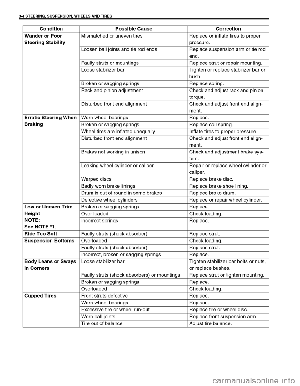
3-4 STEERING, SUSPENSION, WHEELS AND TIRES
Wander or Poor
Steering StabilityMismatched or uneven tires Replace or inflate tires to proper
pressure.
Loosen ball joints and tie rod ends Replace suspension arm or tie rod
end.
Faulty struts or mountings Replace strut or repair mounting.
Loose stabilizer bar Tighten or replace stabilizer bar or
bush.
Broken or sagging springs Replace spring.
Rack and pinion adjustment Check and adjust rack and pinion
torque.
Disturbed front end alignment Check and adjust front end align-
ment.
Erratic Steering When
BrakingWorn wheel bearings Replace.
Broken or sagging springs Replace coil spring.
Wheel tires are inflated unequally Inflate tires to proper pressure.
Disturbed front end alignment Check and adjust front end align-
ment.
Brakes not working in unison Check and adjustment brake sys-
tem.
Leaking wheel cylinder or caliper Repair or replace wheel cylinder or
caliper.
Warped discs Replace brake disc.
Badly worn brake linings Replace brake shoe lining.
Drum is out of round in some brakes Replace brake drum.
Defective wheel cylinders Replace or repair wheel cylinder.
Low or Uneven Trim
Height
NOTE:
See NOTE *1.Broken or sagging springs Replace.
Over loaded Check loading.
Incorrect springs Replace.
Ride Too Soft
Faulty struts (shock absorber) Replace strut.
Suspension Bottoms
Overloaded Check loading.
Faulty struts (shock absorber) Replace strut.
Incorrect, broken or sagging springs Replace.
Body Leans or Sways
in CornersLoose stabilizer bar Tighten stabilizer bar bolts or nuts,
or replace bushes.
Faulty struts (shock absorbers) or mountings Replace strut or tighten mounting.
Broken or sagging springs Replace.
Overloaded Check loading.
Cupped Tires
Front struts defective Replace.
Worn wheel bearings Replace.
Excessive tire or wheel run-out Replace tire or wheel disc.
Worn ball joints Replace front suspension arm.
Tire out of balance Adjust tire balance. Condition Possible Cause Correction
Page 135 of 698
3B-14 MANUAL RACK AND PINION
STEERING PINION
REMOVAL
1) Remove rack plunger as shown in STEERING RACK
PLUNGER.
2) Remove bearing plug with special tool.
Special tool
(A) : 09944-26011
3) Tap on position as shown with plastic hammer (2) to sepa-
rate pinion assembly (1) from housing, and remove pinion
assembly.
4) Remove oil seal (2) with special tool from pinion bearing plug
(1).
Special tool
(B) : 09913-50121
INSPECTION
Inspect pinion teeth surface (3) for wear or damage.
Inspect oil seal (1) for damage.
Replace any part found defective.
Check rotation condition of bearing and inspect for wear.
If found defective, replace.
2. Case seal
Page 141 of 698
3B-20 MANUAL RACK AND PINION
SPECIAL TOOL
09913-65210 09913-50121 09921-20200 09925-98210
Tie-rod end remover Oil seal remover Pinion bearing remover Bearing installer
09930-30102 09943-78210 09944-18211 09944-26011
Sliding shaft Rack bush installer Pinion torque checking
socket43 mm Socket (Pinion
bearing plug remover)
09944-48210
Rack bush remover
Page 151 of 698
3B1-10 ELECTRICAL POWER STEERING (P/S) SYSTEM
SERIAL DATA LINK CIRCUIT CHECK
DIAGNOSTIC FLOW TABLE
CAUTION:
Be sure to perform “SYSTEM CHECK FLOW TABLE” before starting diagnosis according to flow table.
1. Main fuse box 6. Combination meter 11. Data link connector (DLC)
2.“EPS” fuse (30 A) 7. Speedometer 12. To ECM, SDM and ABS hydraulic unit/control module
assembly (if equipped)
3. Ignition switch 8.“EPS” warning lamp 13. P/S control module
4. Circuit fuse box 9. To vehicle speed sensor (VSS) 14. Connector “G24”
5.“IG coil” fuse (15 A) 10. To main fuse box
Step Action Yes No
1Was “SYSTEM CHECK FLOW TABLE” per-
formed?Go to Step 2. Go to “SYSTEM CHECK
FLOW TABLE” in this sec-
tion.
2 1) Make sure that SUZUKI scan tool free from
malfunction and correct cartridge for P/S
system is used.
2) Turn ignition switch to OFF position.
3) Check proper connection of SUZUKI scan
tool to DLC.
Is connection in good condition?Go to Step 3. Properly connect SUZUKI
scan tool to DLC.