Page 504 of 698
ENGINE MECHANICAL (M13 ENGINE) 6A1-3
ENGINE LUBRICATION
The oil pump is of a trochoid type, and mounted on the crankshaft. Oil is drawn up through the oil pump strainer
and passed through the pump to the oil filter.
The filtered oil flows into 2 paths in cylinder block.
In one path, oil reaches the crankshaft journal bearings. Oil from the crankshaft journal bearings is supplied to
the connecting rod bearings by means of intersecting passages drilled in the crankshaft, and then injected from
the big end of connecting rod to lubricate piston, rings, and cylinder wall.
In other path oil goes up to the cylinder head and lubricates valves and camshafts, etc., after passing through
the internal oilway of camshafts.
An oil relief valve is provided on the oil pump. This valve starts relieving oil pressure when the pressure exceeds
about 400 kPa (4.0 kg/cm
2, 56.9 psi).
Page 575 of 698

6A1-74 ENGINE MECHANICAL (M13 ENGINE)
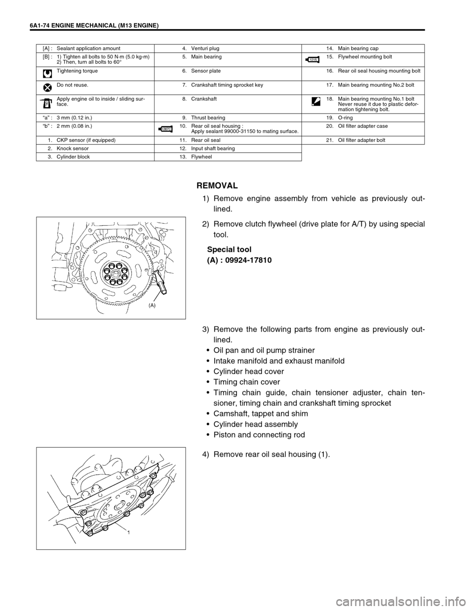
REMOVAL
1) Remove engine assembly from vehicle as previously out-
lined.
2) Remove clutch flywheel (drive plate for A/T) by using special
tool.
Special tool
(A) : 09924-17810
3) Remove the following parts from engine as previously out-
lined.
Oil pan and oil pump strainer
Intake manifold and exhaust manifold
Cylinder head cover
Timing chain cover
Timing chain guide, chain tensioner adjuster, chain ten-
sioner, timing chain and crankshaft timing sprocket
Camshaft, tappet and shim
Cylinder head assembly
Piston and connecting rod
4) Remove rear oil seal housing (1).
[A] : Sealant application amount 4. Venturi plug 14. Main bearing cap
[B] : 1) Tighten all bolts to 50 N·m (5.0 kg-m)
2) Then, turn all bolts to 60°5. Main bearing 15. Flywheel mounting bolt
Tightening torque 6. Sensor plate 16. Rear oil seal housing mounting bolt
Do not reuse. 7. Crankshaft timing sprocket key 17. Main bearing mounting No.2 bolt
Apply engine oil to inside / sliding sur-
face.8. Crankshaft
18. Main bearing mounting No.1 bolt
Never reuse it due to plastic defor-
mation tightening bolt.
“a” : 3 mm (0.12 in.) 9. Thrust bearing 19. O-ring
“b” : 2 mm (0.08 in.) 10. Rear oil seal housing :
Apply sealant 99000-31150 to mating surface.20. Oil filter adapter case
1. CKP sensor (if equipped) 11. Rear oil seal 21. Oil filter adapter bolt
2. Knock sensor 12. Input shaft bearing
3. Cylinder block 13. Flywheel
Page 588 of 698
ENGINE MECHANICAL (M13 ENGINE) 6A1-87
SPECIAL TOOL
09911-97720 09911-97820 09913-75520 09915-47330
Oil seal guide Oil seal installer Bearing installer Oil filter wrench
09915-64510-001 09915-64510-002 09915-64530 09915-67010
Compression gauge Connector Hose Attachment
09915-67310 09915-77310 09915-78211 09916-14510
Vacuum gauge Oil pressure gauge Oil pressure gauge
attachmentValve lifer
09916-14910 09916-34542 09916-34550 09916-37320
Valve lifer attachment Reamer handle Reamer (5.5 mm) Reamer (10.5 mm)
Page 608 of 698

ENGINE FUEL 6C-1
6F1
6F2
6G
6C
6K
7A
7A1
7B1
7C1
7D
7E
7F
8A
8B
8C
8D
8E
9
10
10A
10B
SECTION 6C
ENGINE FUEL
CONTENTS
GENERAL DESCRIPTION .............................. 6C-1
ON-VEHICLE SERVICE .................................. 6C-2
COMPONENTS ........................................... 6C-2
PRECAUTIONS ........................................... 6C-3
FUEL LINES ................................................. 6C-4
FUEL PIPE ................................................... 6C-4
FUEL FILLER CAP ...................................... 6C-5FUEL TANK INLET VALVE ......................... 6C-6
FUEL TANK ................................................. 6C-7
FUEL PUMP ASSEMBLY .......................... 6C-10
DISASSEMBLY AND REASSEMBLY .... 6C-12
SPECIAL TOOL ............................................ 6C-14
TIGHTENING TORQUE SPECIFICATION.... 6C-14
GENERAL DESCRIPTION
The main components of the fuel system are fuel tank, fuel pump assembly (with fuel filter, fuel level gauge, fuel
pressure regulator and tank pressure control valve), fuel/vapor separator fuel feed line and fuel vapor line.
For the details of fuel flow and fuel vapor flow, refer to “GENERAL DESCRIPTION” in Section 6E. WARNING:
For vehicles equipped with Supplemental Restraint (Air Bag) System:
Service on and around the air bag system components or wiring must be performed only by an
authorized SUZUKI dealer. Refer to “Air Bag System Components and Wiring Location View” under
“General Description” in air bag system section in order to confirm whether you are performing ser-
vice on or near the air bag system components or wiring. Please observe all WARNINGS and “Ser-
vice Precautions” under “On-Vehicle Service” in air bag system section before performing service
on or around the air bag system components or wiring. Failure to follow WARNINGS could result in
unintentional activation of the system or could render the system inoperative. Either of these two
conditions may result in severe injury.
Technical service work must be started at least 90 seconds after the ignition switch is turned to the
“LOCK” position and the negative cable is disconnected from the battery. Otherwise, the system
may be activated by reserve energy in the Sensing and Diagnostic Module (SDM).
CAUTION:
The engine of this vehicle requires the use of unleaded fuel only. Use of leaded and/or low lead fuel
can result in engine damage and reduce the effectiveness of the emission control system.
Page 609 of 698
6C-2 ENGINE FUEL
ON-VEHICLE SERVICE
COMPONENTS
1. Fuel tank 7. Fuel vapor line 13. Fuel filler hose clamp screw 19. Fuel pressure regulator
2. Fuel pump assembly 8. EVAP canister 14. Tank cover 20. Fuel pump
3. Breather hose 9. Delivery pipe 15. Fuel filler bracket screw 21. Fuel filter assembly
4. Fuel filler cap 10. Fuel/vapor separator 16. Fuel filler bracket nut 22. Fuel level gauge (Fuel sender gauge)
5. Fuel feed line 11. Fuel pump bolt (6 pcs.) 17. Gasket Do not reuse.
6. Wire harness for fuel pump 12. Fuel tank bolt (4 pcs.) 18. O-ring Tightening torque
Page 618 of 698
ENGINE FUEL 6C-11
3) Remove fuel pump assembly (1) from fuel tank (2).
INSPECTION
Check fuel pump assembly for damage.
Check fuel suction filter (1) for evidence of dirt and contami-
nation.
If present, replace or clean and check for presence of dirt in
fuel tank.
For operation or electrical circuit inspection by referring to
Section 6E1.
For inspection of fuel level gauge (2) by referring to Section
8.
Check tank pressure control valve referring to the following
procedures.
a) Air should pass through valve (2) smoothly from fuel vapor
line hose (3) “A” to “B” when blown hard.
b) Also, when vacuum pump (4) is connected to fuel vapor
hose and pump air through valve, air should pass from “B”
to “A”.
Special tool
(A) : 09917-47910
If air doesn’t pass through valve in Step a) or vacuum is main-
tained in Step b), replace fuel filter assembly (1).
1
2
WARNING:
Do not such air through fuel vapor line hose. Fuel vapor
inside valve is harmful.12
Page 619 of 698
6C-12 ENGINE FUEL
DISASSEMBLY AND REASSEMBLY
Disassemble and reassemble fuel pump assembly, noting the fol-
lowings.
When removing fuel level sensor (3), press snap-fit part (4)
and slide it in the arrow direction as shown in figure.
When installing fuel level sensor to housing, fit fuel level sen-
sor securely.
“A” : Apply oil 5. O-ring 10. Fuel pressure regulator
1. Fuel filter assembly (including check valve) 6. Fuel level sensor (Fuel sender gauge) 11. Gasket
2. Grommet 7. Fuel pump 12. Fuel pump plate
3. Tube 8. Cushion Do not reuse.
4. Housing 9. Bracket
CAUTION:
While removing fuel level gauge, do not contact resis-
tor plate (1) or deform arm (2). It may cause fuel level
gauge to fail.
When removing grommet from fuel tube or bracket sub
assembly, be very careful not to cause damage to
grommet installed section (sealed section in bore).
Should it be damaged, replace it with new one, or fuel
will leak from that part.
Page 626 of 698

ENGINE AND EMISSION CONTROL SYSTEM 6E1-5
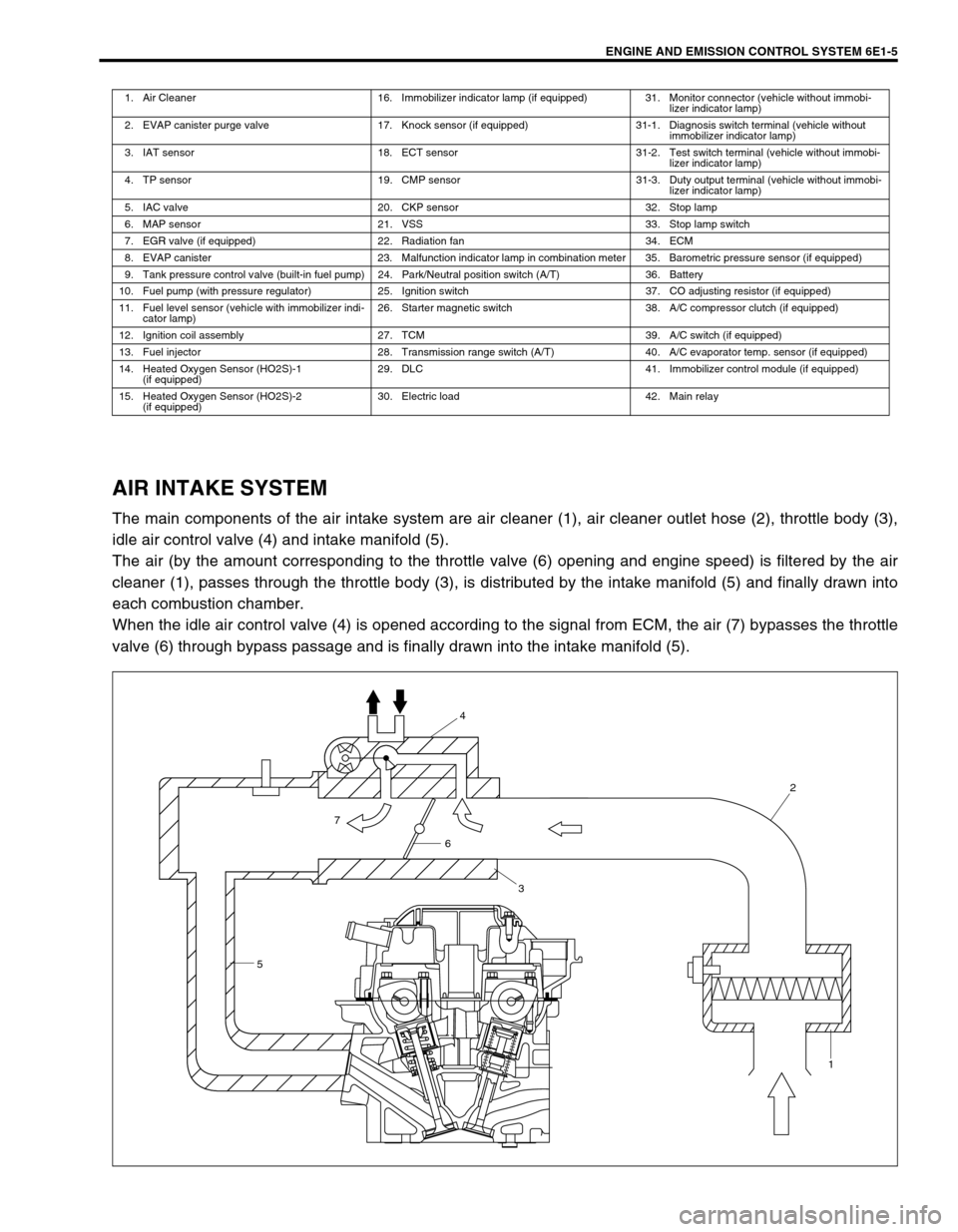
AIR INTAKE SYSTEM
The main components of the air intake system are air cleaner (1), air cleaner outlet hose (2), throttle body (3),
idle air control valve (4) and intake manifold (5).
The air (by the amount corresponding to the throttle valve (6) opening and engine speed) is filtered by the air
cleaner (1), passes through the throttle body (3), is distributed by the intake manifold (5) and finally drawn into
each combustion chamber.
When the idle air control valve (4) is opened according to the signal from ECM, the air (7) bypasses the throttle
valve (6) through bypass passage and is finally drawn into the intake manifold (5).
1. Air Cleaner 16. Immobilizer indicator lamp (if equipped) 31. Monitor connector (vehicle without immobi-
lizer indicator lamp)
2. EVAP canister purge valve 17. Knock sensor (if equipped) 31-1. Diagnosis switch terminal (vehicle without
immobilizer indicator lamp)
3. IAT sensor 18. ECT sensor 31-2. Test switch terminal (vehicle without immobi-
lizer indicator lamp)
4. TP sensor 19. CMP sensor 31-3. Duty output terminal (vehicle without immobi-
lizer indicator lamp)
5. IAC valve 20. CKP sensor 32. Stop lamp
6. MAP sensor 21. VSS 33. Stop lamp switch
7. EGR valve (if equipped) 22. Radiation fan 34. ECM
8. EVAP canister 23. Malfunction indicator lamp in combination meter 35. Barometric pressure sensor (if equipped)
9. Tank pressure control valve (built-in fuel pump) 24. Park/Neutral position switch (A/T) 36. Battery
10. Fuel pump (with pressure regulator) 25. Ignition switch 37. CO adjusting resistor (if equipped)
11. Fuel level sensor (vehicle with immobilizer indi-
cator lamp)26. Starter magnetic switch 38. A/C compressor clutch (if equipped)
12. Ignition coil assembly 27. TCM 39. A/C switch (if equipped)
13. Fuel injector 28. Transmission range switch (A/T) 40. A/C evaporator temp. sensor (if equipped)
14. Heated Oxygen Sensor (HO2S)-1
(if equipped)29. DLC 41. Immobilizer control module (if equipped)
15. Heated Oxygen Sensor (HO2S)-2
(if equipped)30. Electric load 42. Main relay
54
2
1
6
3
7