2000 SUZUKI SWIFT Filter
[x] Cancel search: FilterPage 40 of 698

MAINTENANCE AND LUBRICATION 0B-11
4) Install air cleaner filter fitting protrusion (1) of filter into
groove (2) of case and clamp upper case securely.
REPLACEMENT
Replace air cleaner filter with new one according to steps 1), 2)
and 4) of inspection procedure.
FUEL LINES AND CONNECTIONS
INSPECTION
Visually inspect fuel lines and connections for evidence of fuel
leakage, hose cracking and damage. Make sure all clamps are
secure.
Repair leaky joints, if any.
Replace hoses that are suspected of being cracked.
FUEL FILTER
REPLACEMENT
Fuel filter (1) is installed in fuel pump assembly (2) in fuel tank.
Replace fuel filter with new one, referring to “FUEL PUMP
ASSEMBLY” in Section 6C for proper procedure.
WARNING:
This work must be performed in a well ventilated area
and away from any open flames (such as gas hot water
heaters).
Page 50 of 698

MAINTENANCE AND LUBRICATION 0B-21
STEERING
Check to ensure that steering wheel is free from instability, or abnormally heavy feeling.
Check that the vehicle does not wander or pull to one side.
ENGINE
Check that engine responds readily at all speeds.
Check that engine is free from abnormal noise and abnormal vibration.
BODY, WHEELS AND POWER TRANSMITTING SYSTEM
Check that body, wheels and power transmitting system are free from abnormal noise and abnormal vibration or
any other abnormal condition.
METERS AND GAUGE
Check that speedometer, odometer, fuel meter, temperature gauge, etc. are operating accurately.
LIGHTS
Check that all lights operate properly.
WINDSHIELD DEFROSTER
Periodically check that air comes out from defroster outlet when operating heater or air conditioning.
Set mode control lever to defroster position and fan switch lever to “HI” position for this check.
RECOMMENDED FLUIDS AND LUBRICANTS
Engine oil SE, SF, SG, SH or SJ grade (Refer to “ENGINE OIL AND OIL FILTER”
in this section for engine oil viscosity.)
Engine coolant
(Ethylene glycol base coolant)“Antifreeze/Anticorrosion coolant”
Brake fluid DOT 3
Manual transmission oil Refer to “M/T OIL CHANGE” in Section 7A.
Transfer oil (4WD) Refer to “TRANSFER OIL CHANGE” in Section 7D.
Differential oil (4WD) Refer to “DIFFERENTIAL OIL CHANGE” in Section 7F.
Automatic transmission fluid
An equivalent of DEXRON
®-III
Door hinges Engine oil or water resistance chassis grease
Hood latch assembly Engine oil or water resistance chassis grease
Key lock cylinder Spray lubricant
Page 95 of 698

1B-30 AIR CONDITIONING (OPTIONAL)
RECEIVER/DRYER
REMOVAL
1) Remove condenser assembly referring to “CONDENSER
ASSEMBLY” in this section.
2) Remove condenser mounting bracket (1) from condenser (2)
as shown.
3) Remove receiver/dryer cap (3) using a hexagon wrench.
4) Remove filter (1) from the receiver/dryer (2).
5) Remove dryer (1) using a plier.
INSTALLATION
Reverse removal procedure to install receiver/dryer noting the fol-
lowing instructions.
Do not remove dryer from the plastic bag until just before
inserting it into the receiver.
Install dryer (1) with its double-layer portion facing the bot-
tom of the receiver.
Page 395 of 698

6-26 ENGINE GENERAL INFORMATION AND DIAGNOSIS
ENGINE DIAGNOSIS TABLE
Perform troubleshooting referring to following table when ECM has detected no DTC and no abnormality has
been found in visual inspection and engine basic inspection previously.
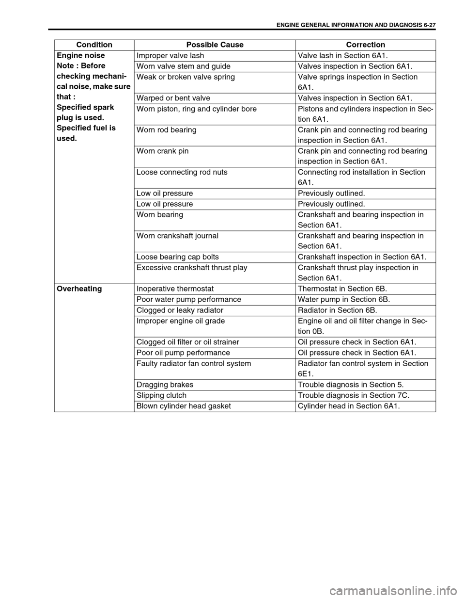
Condition Possible Cause Correction
Hard Starting
(Engine cranks OK) Faulty spark plug Spark plugs in Section 6F1.
Leaky high-tension cord High-tension cords in Section 6F1.
Loose connection or disconnection of high-
tension cords or lead wiresHigh-tension cords in Section 6F1.
Faulty ignition coil Ignition coil in Section 6F1.
Dirty or clogged fuel hose or pipe Diagnostic Flow Table B-3.
Malfunctioning fuel pump Diagnostic Flow Table B-3.
Air inhaling from intake manifold gasket or
throttle body gasket
Faulty idle air control system Diagnostic Flow Table B-4.
Faulty ECT sensor or MAP sensor ECT sensor or MAP sensor in Section
6E1.
Faulty ECM
Hard Starting
(Engine cranks OK) Poor spark plug tightening or faulty gasket Spark plugs in Section 6F1.
Compression leak from valve seat Valves inspection in Section 6A1.
Sticky valve stem Valves inspection in Section 6A1.
Weak or damaged valve springs Valve springs inspection in Section
6A1.
Compression leak at cylinder head gasket Cylinder head inspection in Section
6A1.
Sticking or damaged piston ring Cylinders, pistons and piston rings
inspection in Section 6A1.
Worn piston, ring or cylinder Cylinders, pistons and piston rings
inspection in Section 6A1.
Malfunctioning PCV valve PCV system in Section 6E1.
Low compression Compression check in Section 6A1.
Low oil pressure
Improper oil viscosity Engine oil and oil filter change in Sec-
tion 0B.
Malfunctioning oil pressure switch Oil pressure switch inspection in Sec-
tion 8.
Clogged oil strainer Oil pan and oil pump strainer cleaning
in Section 6A1.
Functional deterioration of oil pump Oil pump in Section 6A1.
Worn oil pump relief valve Oil pump in Section 6A1.
Excessive clearance in various sliding parts
Page 396 of 698

ENGINE GENERAL INFORMATION AND DIAGNOSIS 6-27
Engine noise
Note : Before
checking mechani-
cal noise, make sure
that :
Specified spark
plug is used.
Specified fuel is
used.Improper valve lash Valve lash in Section 6A1.
Worn valve stem and guide Valves inspection in Section 6A1.
Weak or broken valve spring Valve springs inspection in Section
6A1.
Warped or bent valve Valves inspection in Section 6A1.
Worn piston, ring and cylinder bore Pistons and cylinders inspection in Sec-
tion 6A1.
Worn rod bearing Crank pin and connecting rod bearing
inspection in Section 6A1.
Worn crank pin Crank pin and connecting rod bearing
inspection in Section 6A1.
Loose connecting rod nuts Connecting rod installation in Section
6A1.
Low oil pressure Previously outlined.
Low oil pressure Previously outlined.
Worn bearing Crankshaft and bearing inspection in
Section 6A1.
Worn crankshaft journal Crankshaft and bearing inspection in
Section 6A1.
Loose bearing cap bolts Crankshaft inspection in Section 6A1.
Excessive crankshaft thrust play Crankshaft thrust play inspection in
Section 6A1.
Overheating
Inoperative thermostat Thermostat in Section 6B.
Poor water pump performance Water pump in Section 6B.
Clogged or leaky radiator Radiator in Section 6B.
Improper engine oil grade Engine oil and oil filter change in Sec-
tion 0B.
Clogged oil filter or oil strainer Oil pressure check in Section 6A1.
Poor oil pump performance Oil pressure check in Section 6A1.
Faulty radiator fan control system Radiator fan control system in Section
6E1.
Dragging brakes Trouble diagnosis in Section 5.
Slipping clutch Trouble diagnosis in Section 7C.
Blown cylinder head gasket Cylinder head in Section 6A1. Condition Possible Cause Correction
Page 397 of 698

6-28 ENGINE GENERAL INFORMATION AND DIAGNOSIS
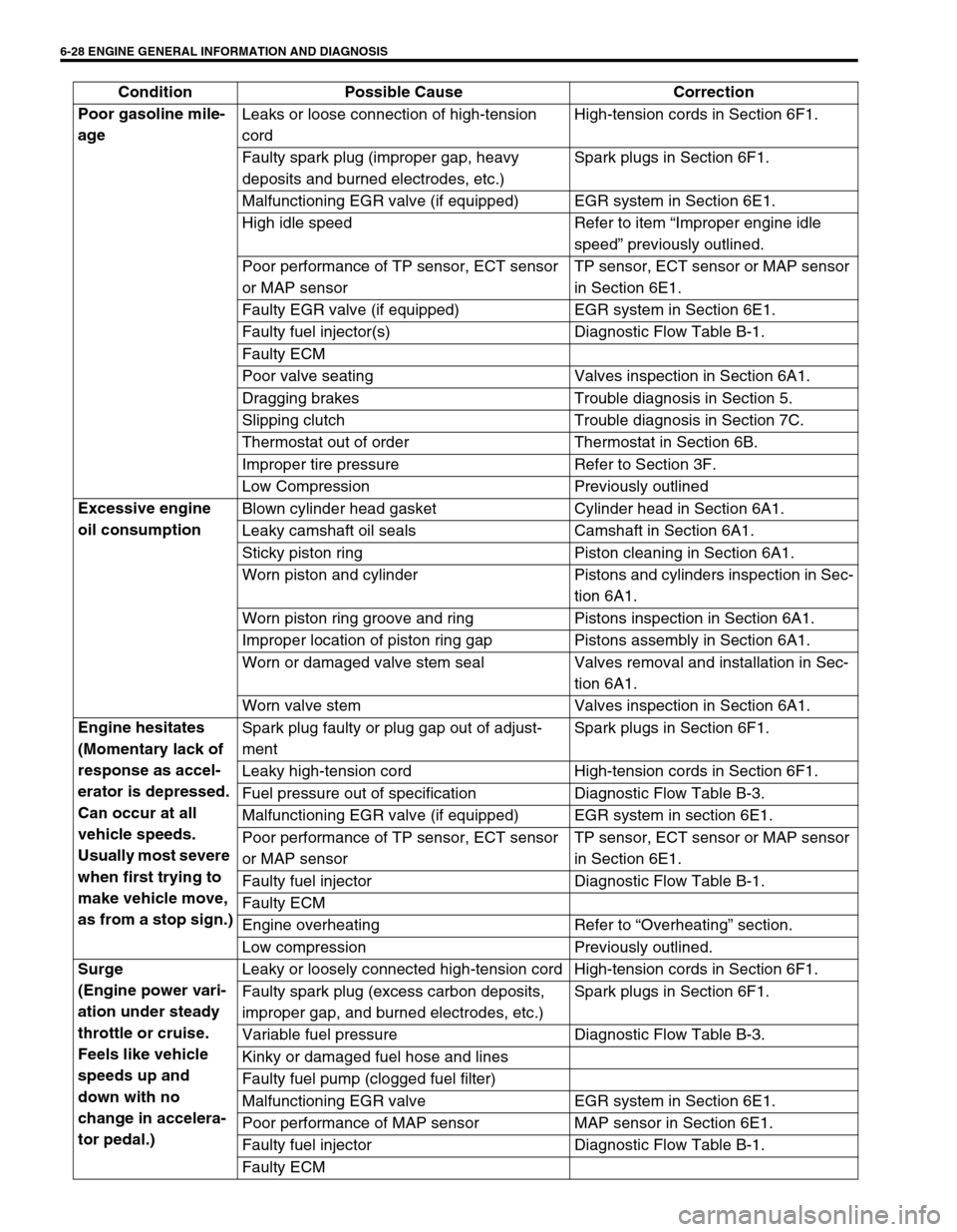
Poor gasoline mile-
age Leaks or loose connection of high-tension
cordHigh-tension cords in Section 6F1.
Faulty spark plug (improper gap, heavy
deposits and burned electrodes, etc.)Spark plugs in Section 6F1.
Malfunctioning EGR valve (if equipped) EGR system in Section 6E1.
High idle speed Refer to item “Improper engine idle
speed” previously outlined.
Poor performance of TP sensor, ECT sensor
or MAP sensorTP sensor, ECT sensor or MAP sensor
in Section 6E1.
Faulty EGR valve (if equipped) EGR system in Section 6E1.
Faulty fuel injector(s) Diagnostic Flow Table B-1.
Faulty ECM
Poor valve seating Valves inspection in Section 6A1.
Dragging brakes Trouble diagnosis in Section 5.
Slipping clutch Trouble diagnosis in Section 7C.
Thermostat out of order Thermostat in Section 6B.
Improper tire pressure Refer to Section 3F.
Low Compression Previously outlined
Excessive engine
oil consumption Blown cylinder head gasket Cylinder head in Section 6A1.
Leaky camshaft oil seals Camshaft in Section 6A1.
Sticky piston ring Piston cleaning in Section 6A1.
Worn piston and cylinder Pistons and cylinders inspection in Sec-
tion 6A1.
Worn piston ring groove and ring Pistons inspection in Section 6A1.
Improper location of piston ring gap Pistons assembly in Section 6A1.
Worn or damaged valve stem seal Valves removal and installation in Sec-
tion 6A1.
Worn valve stem Valves inspection in Section 6A1.
Engine hesitates
(Momentary lack of
response as accel-
erator is depressed.
Can occur at all
vehicle speeds.
Usually most severe
when first trying to
make vehicle move,
as from a stop sign.)Spark plug faulty or plug gap out of adjust-
mentSpark plugs in Section 6F1.
Leaky high-tension cord High-tension cords in Section 6F1.
Fuel pressure out of specification Diagnostic Flow Table B-3.
Malfunctioning EGR valve (if equipped) EGR system in section 6E1.
Poor performance of TP sensor, ECT sensor
or MAP sensorTP sensor, ECT sensor or MAP sensor
in Section 6E1.
Faulty fuel injector Diagnostic Flow Table B-1.
Faulty ECM
Engine overheating Refer to “Overheating” section.
Low compression Previously outlined.
Surge
(Engine power vari-
ation under steady
throttle or cruise.
Feels like vehicle
speeds up and
down with no
change in accelera-
tor pedal.)Leaky or loosely connected high-tension cord High-tension cords in Section 6F1.
Faulty spark plug (excess carbon deposits,
improper gap, and burned electrodes, etc.)Spark plugs in Section 6F1.
Variable fuel pressure Diagnostic Flow Table B-3.
Kinky or damaged fuel hose and lines
Faulty fuel pump (clogged fuel filter)
Malfunctioning EGR valve EGR system in Section 6E1.
Poor performance of MAP sensor MAP sensor in Section 6E1.
Faulty fuel injector Diagnostic Flow Table B-1.
Faulty ECM Condition Possible Cause Correction
Page 398 of 698

ENGINE GENERAL INFORMATION AND DIAGNOSIS 6-29
Excessive detona-
tion
(Engine makes con-
tinuously sharp
metallic knocks that
change with throttle
opening. Sounds
like pop corn pop-
ping.)Faulty spark plug Spark plugs in Section 6F1.
Loose connection of high-tension cord High-tension cords in Section 6F1.
Engine overheating Refer to “Overheating” section.
Clogged fuel filter (faulty fuel pump) or fuel
linesDiagnostic Flow Table B-1 or B-2.
Air inhaling from intake manifold or throttle
body gasket
Malfunctioning EGR valve (if equipped) EGR system in Section 6E1.
Poor performance of knock sensor, ECT sen-
sor or MAP sensorKnock sensor in Section 6, ECT sensor
or MAP sensor in Section 6E1.
Faulty fuel injector(s) Diagnostic Flow Table B-1.
Faulty ECM
Excessive combustion chamber deposits Piston and cylinder head cleaning in
Section 6A1.
Engine has no
powerFaulty spark plug Spark plugs in Section 6F1.
Faulty ignition coil with ignitor Ignition coil in Section 6F1.
Leaks, loose connection or disconnection of
high-tension cordHigh-tension cords in Section 6F1.
Faulty knock sensor Knock sensor malfunction in this sec-
tion.
Clogged fuel hose or pipe Diagnostic Flow Table B-3.
Malfunctioning fuel pump Diagnostic Flow Table B-2.
Air inhaling from intake manifold gasket or
throttle body gasket
Engine overheating Refer to “Overheating” section.
Engine has no
powerMalfunctioning EGR valve (if equipped) EGR system inspection in Section 6E1.
Maladjusted accelerator cable play Accelerator cable play in Section 6E1.
Poor performance of TP sensor, ECT sensor
or MAP sensorTP sensor, ECT sensor or MAP sensor
in Section 6E1.
Faulty fuel injector(s) Diagnostic Flow Table B-1.
Faulty ECM
Dragging brakes Trouble diagnosis in Section 5.
Slipping clutch Trouble diagnosis in Section 7C.
Low compression Previously outlined. Condition Possible Cause Correction
Page 489 of 698

6-120 ENGINE GENERAL INFORMATION AND DIAGNOSIS
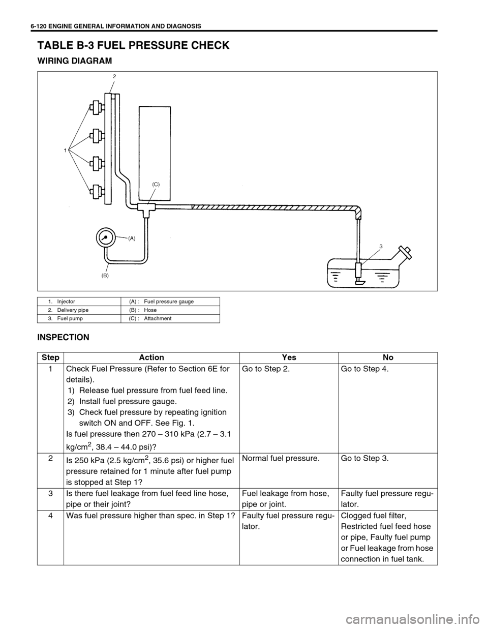
TABLE B-3 FUEL PRESSURE CHECK
WIRING DIAGRAM
INSPECTION
1. Injector (A) : Fuel pressure gauge
2. Delivery pipe (B) : Hose
3. Fuel pump (C) : Attachment
Step Action Yes No
1 Check Fuel Pressure (Refer to Section 6E for
details).
1) Release fuel pressure from fuel feed line.
2) Install fuel pressure gauge.
3) Check fuel pressure by repeating ignition
switch ON and OFF. See Fig. 1.
Is fuel pressure then 270 – 310 kPa (2.7 – 3.1
kg/cm
2, 38.4 – 44.0 psi)?Go to Step 2. Go to Step 4.
2
Is 250 kPa (2.5 kg/cm
2, 35.6 psi) or higher fuel
pressure retained for 1 minute after fuel pump
is stopped at Step 1?Normal fuel pressure. Go to Step 3.
3 Is there fuel leakage from fuel feed line hose,
pipe or their joint?Fuel leakage from hose,
pipe or joint.Faulty fuel pressure regu-
lator.
4 Was fuel pressure higher than spec. in Step 1? Faulty fuel pressure regu-
lator.Clogged fuel filter,
Restricted fuel feed hose
or pipe, Faulty fuel pump
or Fuel leakage from hose
connection in fuel tank.