2000 SUZUKI SWIFT warning light
[x] Cancel search: warning lightPage 155 of 698
3B1-14 ELECTRICAL POWER STEERING (P/S) SYSTEM
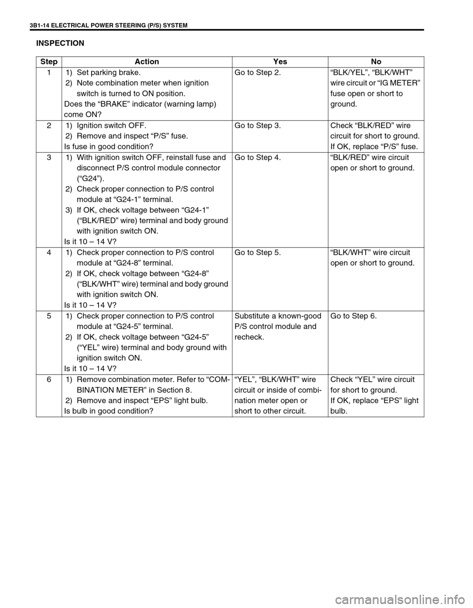
INSPECTION
Step Action Yes No
1 1) Set parking brake.
2) Note combination meter when ignition
switch is turned to ON position.
Does the “BRAKE” indicator (warning lamp)
come ON?Go to Step 2.“BLK/YEL”, “BLK/WHT”
wire circuit or “IG METER”
fuse open or short to
ground.
2 1) Ignition switch OFF.
2) Remove and inspect “P/S” fuse.
Is fuse in good condition?Go to Step 3. Check “BLK/RED” wire
circuit for short to ground.
If OK, replace “P/S” fuse.
3 1) With ignition switch OFF, reinstall fuse and
disconnect P/S control module connector
(“G24”).
2) Check proper connection to P/S control
module at “G24-1” terminal.
3) If OK, check voltage between “G24-1”
(“BLK/RED” wire) terminal and body ground
with ignition switch ON.
Is it 10 – 14 V?Go to Step 4.“BLK/RED” wire circuit
open or short to ground.
4 1) Check proper connection to P/S control
module at “G24-8” terminal.
2) If OK, check voltage between “G24-8”
(“BLK/WHT” wire) terminal and body ground
with ignition switch ON.
Is it 10 – 14 V?Go to Step 5.“BLK/WHT” wire circuit
open or short to ground.
5 1) Check proper connection to P/S control
module at “G24-5” terminal.
2) If OK, check voltage between “G24-5”
(“YEL” wire) terminal and body ground with
ignition switch ON.
Is it 10 – 14 V?Substitute a known-good
P/S control module and
recheck.Go to Step 6.
6 1) Remove combination meter. Refer to “COM-
BINATION METER” in Section 8.
2) Remove and inspect “EPS” light bulb.
Is bulb in good condition?“YEL”, “BLK/WHT” wire
circuit or inside of combi-
nation meter open or
short to other circuit.Check “YEL” wire circuit
for short to ground.
If OK, replace “EPS” light
bulb.
Page 168 of 698
ELECTRICAL POWER STEERING (P/S) SYSTEM 3B1-27
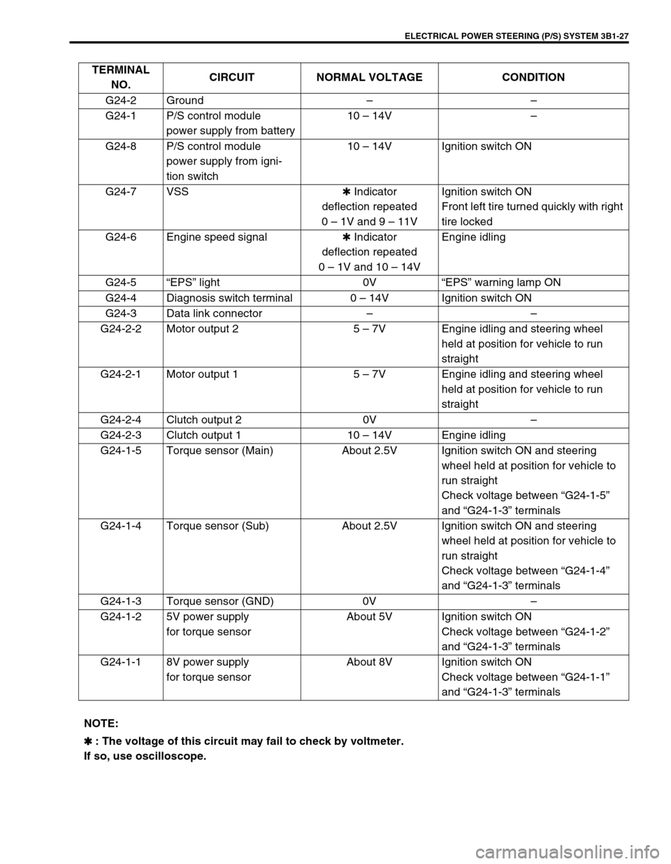
TERMINAL
NO.CIRCUIT NORMAL VOLTAGE CONDITION
G24-2 Ground––
G24-1 P/S control module
power supply from battery10 – 14V–
G24-8 P/S control module
power supply from igni-
tion switch10 – 14V Ignition switch ON
G24-7 VSS✱ Indicator
deflection repeated
0 – 1V and 9 – 11VIgnition switch ON
Front left tire turned quickly with right
tire locked
G24-6 Engine speed signal✱ Indicator
deflection repeated
0 – 1V and 10 – 14VEngine idling
G24-5“EPS” light 0V“EPS” warning lamp ON
G24-4 Diagnosis switch terminal 0 – 14V Ignition switch ON
G24-3 Data link connector––
G24-2-2 Motor output 2 5 – 7V Engine idling and steering wheel
held at position for vehicle to run
straight
G24-2-1 Motor output 1 5 – 7V Engine idling and steering wheel
held at position for vehicle to run
straight
G24-2-4 Clutch output 2 0V–
G24-2-3 Clutch output 1 10 – 14V Engine idling
G24-1-5 Torque sensor (Main) About 2.5V Ignition switch ON and steering
wheel held at position for vehicle to
run straight
Check voltage between “G24-1-5”
and “G24-1-3” terminals
G24-1-4 Torque sensor (Sub) About 2.5V Ignition switch ON and steering
wheel held at position for vehicle to
run straight
Check voltage between “G24-1-4”
and “G24-1-3” terminals
G24-1-3 Torque sensor (GND) 0V–
G24-1-2 5V power supply
for torque sensorAbout 5V Ignition switch ON
Check voltage between “G24-1-2”
and “G24-1-3” terminals
G24-1-1 8V power supply
for torque sensorAbout 8V Ignition switch ON
Check voltage between “G24-1-1”
and “G24-1-3” terminals
NOTE:
✱
✱✱ ✱ : The voltage of this circuit may fail to check by voltmeter.
If so, use oscilloscope.
Page 253 of 698
3F-8 WHEELS AND TIRES
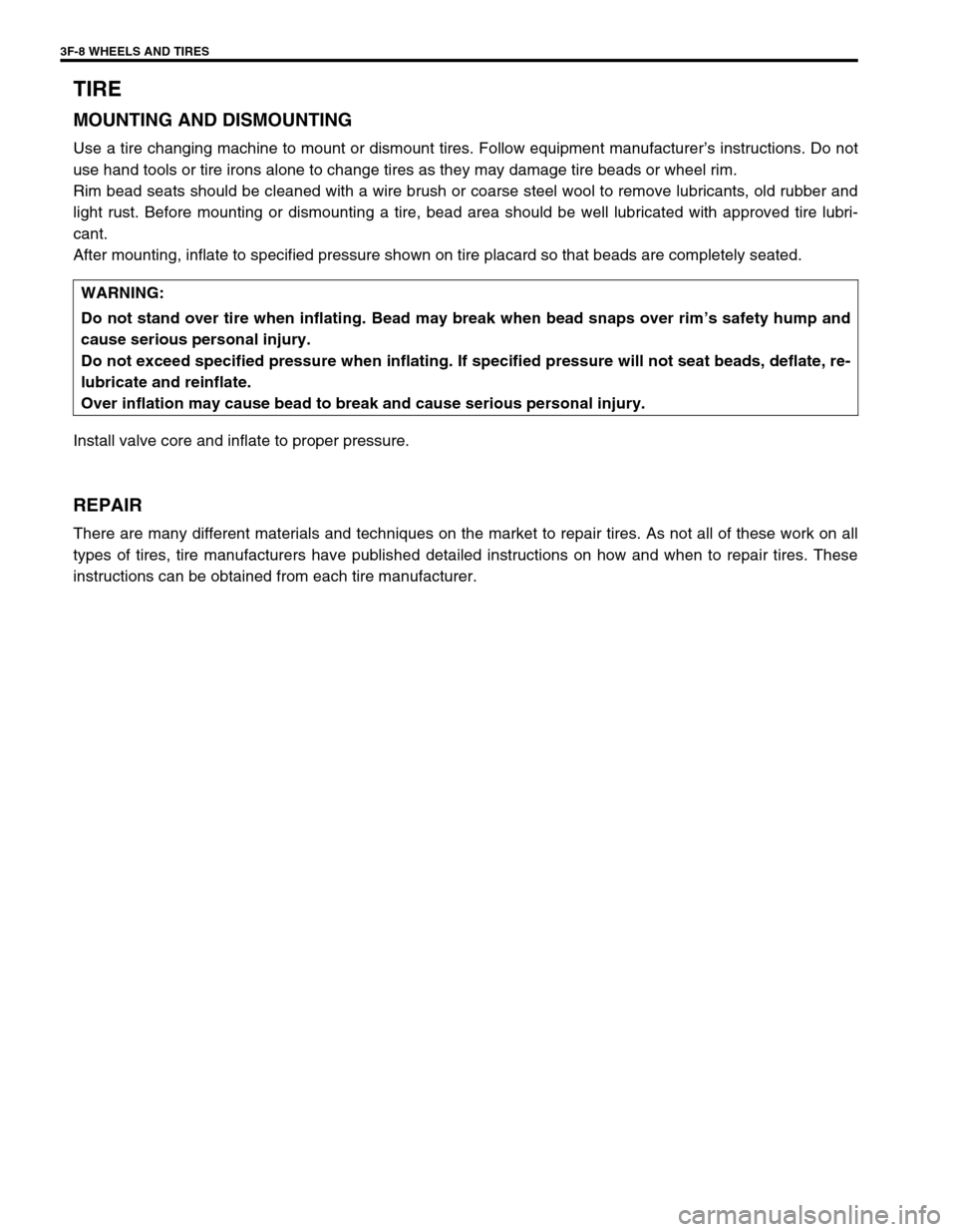
TIRE
MOUNTING AND DISMOUNTING
Use a tire changing machine to mount or dismount tires. Follow equipment manufacturer’s instructions. Do not
use hand tools or tire irons alone to change tires as they may damage tire beads or wheel rim.
Rim bead seats should be cleaned with a wire brush or coarse steel wool to remove lubricants, old rubber and
light rust. Before mounting or dismounting a tire, bead area should be well lubricated with approved tire lubri-
cant.
After mounting, inflate to specified pressure shown on tire placard so that beads are completely seated.
Install valve core and inflate to proper pressure.
REPAIR
There are many different materials and techniques on the market to repair tires. As not all of these work on all
types of tires, tire manufacturers have published detailed instructions on how and when to repair tires. These
instructions can be obtained from each tire manufacturer.WARNING:
Do not stand over tire when inflating. Bead may break when bead snaps over rim’s safety hump and
cause serious personal injury.
Do not exceed specified pressure when inflating. If specified pressure will not seat beads, deflate, re-
lubricate and reinflate.
Over inflation may cause bead to break and cause serious personal injury.
Page 279 of 698
5-6 BRAKES
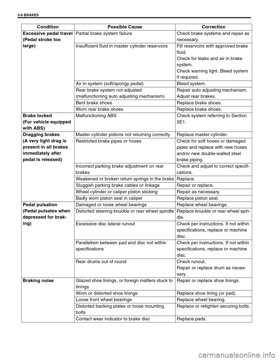
Excessive pedal travel
(Pedal stroke too
large)Partial brake system failure Check brake systems and repair as
necessary.
Insufficient fluid in master cylinder reservoirs Fill reservoirs with approved brake
fluid.
Check for leaks and air in brake
system.
Check warning light. Bleed system
if required.
Air in system (soft/spongy pedal) Bleed system.
Rear brake system not adjusted
(malfunctioning auto adjusting mechanism)Repair auto adjusting mechanism.
Adjust rear brakes.
Bent brake shoes Replace brake shoes.
Worn rear brake shoes Replace brake shoes.
Brake locked
(For vehicle equipped
with ABS)Malfunctioning ABS Check system referring to Section
5E1.
Dragging brakes
(A very light drag is
present in all brakes
immediately after
pedal is released)Master cylinder pistons not returning correctly Replace master cylinder.
Restricted brake pipes or hoses Check for soft hoses or damaged
pipes and replace with new hoses
and/or new double-walled steel
brake piping.
Incorrect parking brake adjustment on rear
brakesCheck and adjust to correct specifi-
cations.
Weakened or broken return springs in the brake Replace.
Sluggish parking brake cables or linkage Repair or replace.
Wheel cylinder or caliper piston sticking Repair as necessary.
Badly worn piston seal in caliper Replace piston seal.
Pedal pulsation
(Pedal pulsates when
depressed for brak-
ing)Damaged or loose wheel bearings Replace wheel bearings.
Distorted steering knuckle or rear wheel spindle Replace knuckle or rear wheel spin-
dle.
Excessive disc lateral runout Check per instructions. If not within
specifications, replace or machine
disc.
Parallelism between pad and disc not within
specificationsCheck per instructions. If not within
specifications, replace or machine
disc.
Rear drums out of round Check runout.
Repair or replace drum as neces-
sary.
Braking noise
Glazed shoe linings, or foreign matters stuck to
liningsRepair or replace shoe linings.
Worn or distorted shoe linings Replace shoe lining (or pad).
Loose front wheel bearings Replace wheel bearing.
Distorted backing plates or loose mounting
boltsReplace or retighten securing bolts.
Contact wear indicator to brake disc Replace pads. Condition Possible Cause Correction
Page 280 of 698
BRAKES 5-7
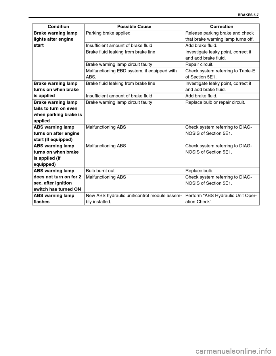
Brake warning lamp
lights after engine
startParking brake applied Release parking brake and check
that brake warning lamp turns off.
Insufficient amount of brake fluid Add brake fluid.
Brake fluid leaking from brake line Investigate leaky point, correct it
and add brake fluid.
Brake warning lamp circuit faulty Repair circuit.
Malfunctioning EBD system, if equipped with
ABS.Check system referring to Table-E
of Section 5E1.
Brake warning lamp
turns on when brake
is appliedBrake fluid leaking from brake line Investigate leaky point, correct it
and add brake fluid.
Insufficient amount of brake fluid Add brake fluid.
Brake warning lamp
fails to turn on even
when parking brake is
appliedBrake warning lamp circuit faulty Replace bulb or repair circuit.
ABS warning lamp
turns on after engine
start (If equipped)Malfunctioning ABS Check system referring to DIAG-
NOSIS of Section 5E1.
ABS warning lamp
turns on when brake
is applied (If
equipped)Malfunctioning ABS Check system referring to DIAG-
NOSIS of Section 5E1.
ABS warning lamp
does not turn on for 2
sec. after ignition
switch has turned ONBulb burnt out Replace bulb.
Malfunctioning ABS Check system referring to DIAG-
NOSIS of Section 5E1.
ABS warning lamp
flashesNew ABS hydraulic unit/control module assem-
bly installed.Perform “ABS Hydraulic Unit Oper-
ation Check”. Condition Possible Cause Correction
Page 287 of 698
5-14 BRAKES
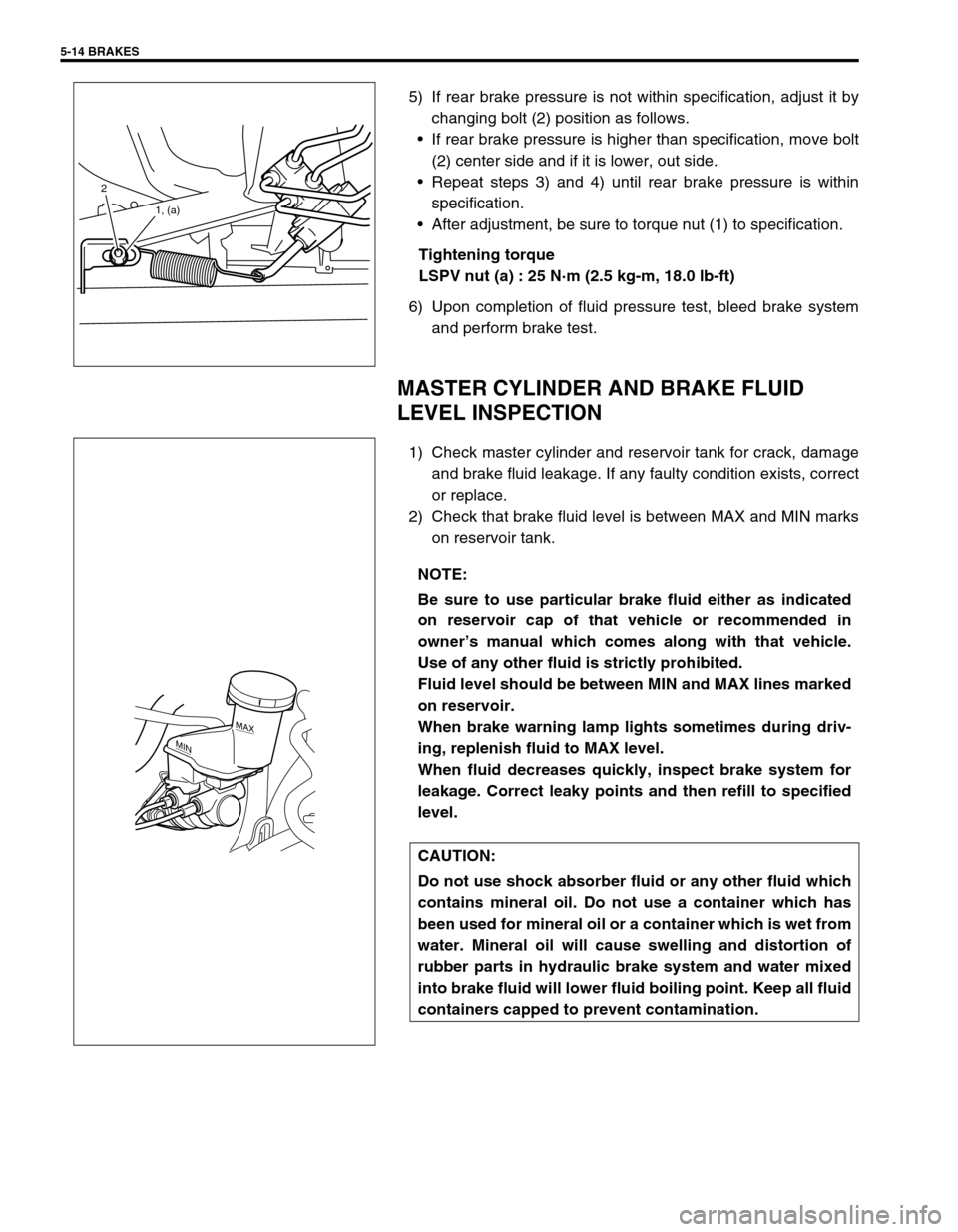
5) If rear brake pressure is not within specification, adjust it by
changing bolt (2) position as follows.
If rear brake pressure is higher than specification, move bolt
(2) center side and if it is lower, out side.
Repeat steps 3) and 4) until rear brake pressure is within
specification.
After adjustment, be sure to torque nut (1) to specification.
Tightening torque
LSPV nut (a) : 25 N·m (2.5 kg-m, 18.0 lb-ft)
6) Upon completion of fluid pressure test, bleed brake system
and perform brake test.
MASTER CYLINDER AND BRAKE FLUID
LEVEL INSPECTION
1) Check master cylinder and reservoir tank for crack, damage
and brake fluid leakage. If any faulty condition exists, correct
or replace.
2) Check that brake fluid level is between MAX and MIN marks
on reservoir tank.
2
1, (a)
NOTE:
Be sure to use particular brake fluid either as indicated
on reservoir cap of that vehicle or recommended in
owner’s manual which comes along with that vehicle.
Use of any other fluid is strictly prohibited.
Fluid level should be between MIN and MAX lines marked
on reservoir.
When brake warning lamp lights sometimes during driv-
ing, replenish fluid to MAX level.
When fluid decreases quickly, inspect brake system for
leakage. Correct leaky points and then refill to specified
level.
CAUTION:
Do not use shock absorber fluid or any other fluid which
contains mineral oil. Do not use a container which has
been used for mineral oil or a container which is wet from
water. Mineral oil will cause swelling and distortion of
rubber parts in hydraulic brake system and water mixed
into brake fluid will lower fluid boiling point. Keep all fluid
containers capped to prevent contamination.
MAX
MIN
Page 328 of 698
ANTILOCK BRAKE SYSTEM (ABS) 5E-3
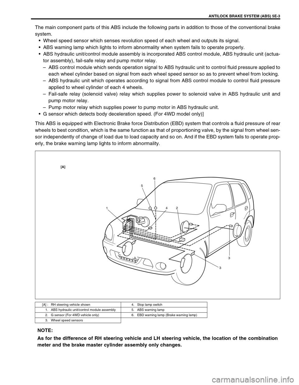
The main component parts of this ABS include the following parts in addition to those of the conventional brake
system.
Wheel speed sensor which senses revolution speed of each wheel and outputs its signal.
ABS warning lamp which lights to inform abnormality when system fails to operate properly.
ABS hydraulic unit/control module assembly is incorporated ABS control module, ABS hydraulic unit (actua-
tor assembly), fail-safe relay and pump motor relay.
–ABS control module which sends operation signal to ABS hydraulic unit to control fluid pressure applied to
each wheel cylinder based on signal from each wheel speed sensor so as to prevent wheel from locking.
–ABS hydraulic unit which operates according to signal from ABS control module to control fluid pressure
applied to wheel cylinder of each 4 wheels.
–Fail-safe relay (solenoid valve) relay which supplies power to solenoid valve in ABS hydraulic unit and
pump motor relay.
–Pump motor relay which supplies power to pump motor in ABS hydraulic unit.
G sensor which detects body deceleration speed. (For 4WD model only)]
This ABS is equipped with Electronic Brake force Distribution (EBD) system that controls a fluid pressure of rear
wheels to best condition, which is the same function as that of proportioning valve, by the signal from wheel sen-
sor independently of change of load due to load capacity and so on. And if the EBD system fails to operate prop-
erly, the brake warning lamp lights to inform abnormality.
[A] : RH steering vehicle shown 4. Stop lamp switch
1. ABS hydraulic unit/control module assembly 5. ABS warning lamp
2. G sensor (For 4WD vehicle only) 6. EBD warning lamp (Brake warning lamp)
3. Wheel speed sensors
156
2 4
33
[A]
NOTE:
As for the difference of RH steering vehicle and LH steering vehicle, the location of the combination
meter and the brake master cylinder assembly only changes.
Page 330 of 698

ANTILOCK BRAKE SYSTEM (ABS) 5E-5
ABS HYDRAULIC UNIT/CONTROL MODULE
ASSEMBLY
ABS control module is a component of ABS hydraulic unit/control
module assembly and has the following functions.
SELF-DIAGNOSIS FUNCTION
ABS control module diagnoses conditions of the system compo-
nent parts (whether or not there is any abnormality) all the time
and indicates the results (warning of abnormality occurrence and
DTC) through the ABS warning lamp as described below.
1) When ignition switch is turned ON, ABS warning lamp lights
for 2 seconds to check its bulb and circuit.
2) When no abnormality has been detected (the system is in
good condition), ABS warning lamp turns OFF after 2 sec-
onds.
3) When an abnormality in the system is detected, ABS warn-
ing lamp lights and the area where that abnormality lies is
stored in the memory of EEPROM in ABS control module.
4) When Diag. switch terminal (2) of diagnosis connector (1)
(monitor connector) is grounded, the abnormal area is output
as DTC. It is indicated by flashing of ABS warning lamp.
(Refer to the table below.)
5) For procedure to clear all DTC’s, refer to “DIAGNOSTIC
TROUBLE CODE CLEARANCE” in this section.
Also ABS control module turns ON EBD warning lamp (brake
warning lamp) depending on the trouble that detected by the
module and EBD warning lamp does not indicate DTC as well as
ABS warning lamp.
FAIL-SAFE FUNCTION
When an abnormality occurs (an abnormal DTC is detected),
ABS control module turns OFF the fail-safe relay which supplies
power to ABS hydraulic unit. Thus, with ABS not operating,
brakes function just like the brake system of the vehicle without
ABS.
SYSTEM CONDITIONABS WARNING LAMP
Diag. switch
terminal is
not groundedDiag. switch
terminal is
grounded
In good
condition
at presentNo trouble in the past OFF DTC 12
Trouble occurred in
the pastOFF History DTC
Abnormal-
ity exists
at presentNo trouble in the past ON Current DTC
Trouble occurred in
the pastONCurrent and
history DTCs
3. Ground terminal
4. Service wire
3 11
2
4