Page 290 of 698
BRAKES 5-17
FRONT BRAKE
BRAKE PAD
REMOVAL
1) Loosen wheel nuts and with vehicle lifted up, remove
wheels.
2) Remove caliper pin bolts (1).
1. Brake caliper carrier 9. Bleeder plug cap
2. Boot 10. Pad spring
3. Caliper 11. Anti noise shim
4. Disc brake piston 12. Caliper pin bolt
5. Piston seal
: Apply fluid (Brake, power steering or automatic transmission fluid).13. Brake disc
6. Cylinder boot
: Apply fluid (Brake, power steering or automatic transmission fluid).14. Slide pin
: Apply lithium grease (99000-25010).
7. Brake pad Tightening torque
8. Bleeder plugDo not reuse.
9
1
7
13
2
143
1226 N·m(2.6 kg-m)
85 N·m(8.5 kg-m)
8
8.5 N·m(0.85 kg-m)
10
5 4
6
11
Page 388 of 698

ENGINE GENERAL INFORMATION AND DIAGNOSIS 6-19
P1451 Barometric pressure sen-
sor performance problemDifference between manifold absolute
pressure (MAP sensor value) and baro-
metric pressure (barometric pressure sen-
sor value) is larger than specification
during cranking.2 driving
cyclesNot
applicable
P1500 Starter signal circuit mal-
functionStarter signal is not inputted from engine
cranking till its start and after or it is always
inputted2 driving
cyclesNot
applicable
P1510 ECM backup power source
malfunctionNo backup power after starting engine 1 driving
cycleNot
applicable
P1600 Serial communication prob-
lem between ECM and
TCMNo signal or check sum error while engine
running1 driving
cycleNot
applicable
P1717 AT D-range signal circuit
malfunctionNo “D” range (park/neutral position signal)
is inputted while vehicle running2 driving
cyclesNot
applicable DTC
NO.DETECTING ITEM DETECTING CONDITION
(DTC will set when detecting :)MIL
(vehicle
with immo-
bilizer indi-
cator lamp)MIL
(vehicle
without
immobi-
lizer indica-
tor lamp)
DTC NO. DETECTING ITEM DETECTING CONDITION
(DTC will set when detecting :)MIL
✱P0702 Transmission Control System Electrical
Refer to Section 7B ✱P0705 Transmission Range Sensor Circuit Malfunc-
tion
✱P0710 Transmission Fluid Temperature Sensor Cir-
cuit Malfunction
✱P0715 Input/turbine Speed Sensor Circuit Malfunc-
tion
✱P0720 Output Shaft Speed Sensor Circuit Malfunc-
tion
✱P0725 Engine Speed Input Circuit Malfunction
✱P0730 Incorrect Gear Ratio
✱P0741 Torque Converter Clutch System Perfor-
mance or Stuck Off
✱P0743 Torque Converter Clutch System Electrical
✱P0753 Shift Solenoid A Electrical
✱P0758 Shift Solenoid B Electrical
✱P0763 Shift Solenoid C Electrical
✱P0768 Shift Solenoid D Electrical
✱P0773 Shift Solenoid E Electrical
✱P1700 Throttle Position Signal Input Malfunction
✱P1702 Internal Control Module Memory Check Some
Error
✱P1709 Engine Coolant Temperature Signal Input
Malfunction
Page 569 of 698

6A1-68 ENGINE MECHANICAL (M13 ENGINE)
UNIT REPAIR OVERHAUL
ENGINE ASSEMBLY
REMOVAL
1) Relieve fuel pressure according to procedure described in
Section 6.
2) Disconnect negative and positive cables at battery.
3) Remove engine hood after disconnecting windshield washer
hose.
4) Remove right and left side engine under covers.
5) Remove A/C compressor belt (if equipped).
6) Remove water pump belt.
7) Drain engine oil, transmission oil or A/T fluid (for A/T vehicle)
and transfer oil (for 4WD vehicle).
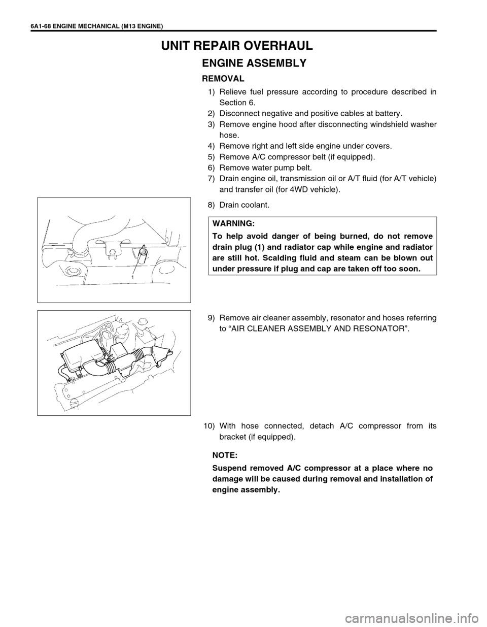
8) Drain coolant.
9) Remove air cleaner assembly, resonator and hoses referring
to “AIR CLEANER ASSEMBLY AND RESONATOR”.
10) With hose connected, detach A/C compressor from its
bracket (if equipped). WARNING:
To help avoid danger of being burned, do not remove
drain plug (1) and radiator cap while engine and radiator
are still hot. Scalding fluid and steam can be blown out
under pressure if plug and cap are taken off too soon.
NOTE:
Suspend removed A/C compressor at a place where no
damage will be caused during removal and installation of
engine assembly.