Page 269 of 698
4A-16 FRONT DRIVE SHAFT
TIGHTENING TORQUE SPECIFICATION
REQUIRED SERVICE MATERIAL
SPECIAL TOOL
Fastening portionTightening torque
Nm kg-m lb-ft
Transfer oil filler/level and drain plugs 21 2.1 15.5
Transmission oil filler/level and drain plugs 23 2.3 17.0
Ball stud bolt 60 6.0 43.5
Tie rod end castle nut 35 - 50 3.5 - 5.0 25.5 - 36.0
Drive shaft nut 175 17.5 127.0
Wheel nut 85 8.5 61.5
Center bearing support bolts 50 5.0 36.0
MaterialRecommended SUZUKI product
(Part Number)Use
Lithium grease SUZUKI SUPER GREASE A
(99000-25010)Oil seal lips
Sealant SUZUKI BOND NO. 1215
(99000-31110)Oil drain and filler plug for manual
transmission or transfer
09913-65210 09900-06107 09900-06108
Tie-rod end remover Snap ring pliers (Open
type)Snap ring pliers (Closing
type)
Page 287 of 698

5-14 BRAKES
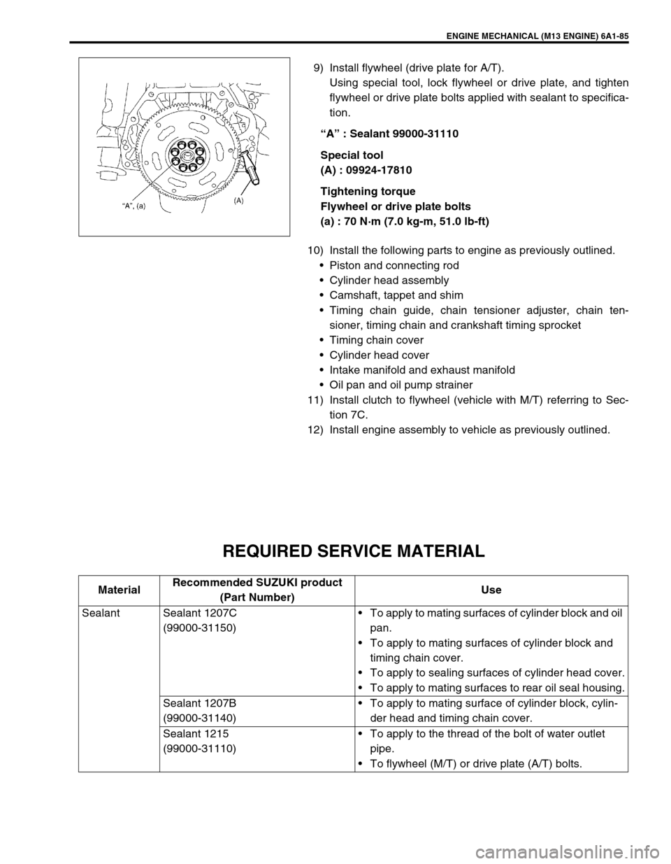
5) If rear brake pressure is not within specification, adjust it by
changing bolt (2) position as follows.
If rear brake pressure is higher than specification, move bolt
(2) center side and if it is lower, out side.
Repeat steps 3) and 4) until rear brake pressure is within
specification.
After adjustment, be sure to torque nut (1) to specification.
Tightening torque
LSPV nut (a) : 25 N·m (2.5 kg-m, 18.0 lb-ft)
6) Upon completion of fluid pressure test, bleed brake system
and perform brake test.
MASTER CYLINDER AND BRAKE FLUID
LEVEL INSPECTION
1) Check master cylinder and reservoir tank for crack, damage
and brake fluid leakage. If any faulty condition exists, correct
or replace.
2) Check that brake fluid level is between MAX and MIN marks
on reservoir tank.
2
1, (a)
NOTE:
Be sure to use particular brake fluid either as indicated
on reservoir cap of that vehicle or recommended in
owner’s manual which comes along with that vehicle.
Use of any other fluid is strictly prohibited.
Fluid level should be between MIN and MAX lines marked
on reservoir.
When brake warning lamp lights sometimes during driv-
ing, replenish fluid to MAX level.
When fluid decreases quickly, inspect brake system for
leakage. Correct leaky points and then refill to specified
level.
CAUTION:
Do not use shock absorber fluid or any other fluid which
contains mineral oil. Do not use a container which has
been used for mineral oil or a container which is wet from
water. Mineral oil will cause swelling and distortion of
rubber parts in hydraulic brake system and water mixed
into brake fluid will lower fluid boiling point. Keep all fluid
containers capped to prevent contamination.
MAX
MIN
Page 586 of 698

ENGINE MECHANICAL (M13 ENGINE) 6A1-85
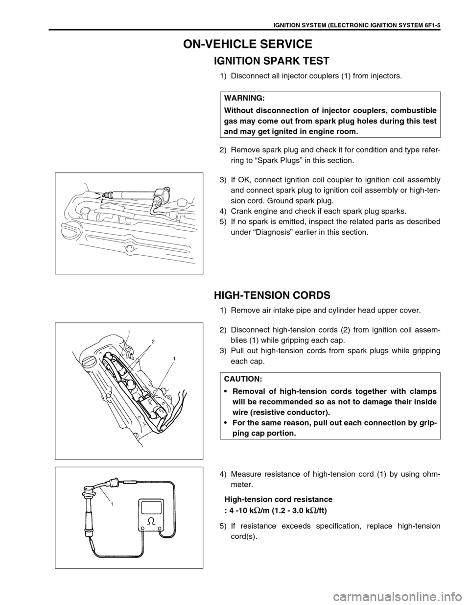
9) Install flywheel (drive plate for A/T).
Using special tool, lock flywheel or drive plate, and tighten
flywheel or drive plate bolts applied with sealant to specifica-
tion.
“A” : Sealant 99000-31110
Special tool
(A) : 09924-17810
Tightening torque
Flywheel or drive plate bolts
(a) : 70 N·m (7.0 kg-m, 51.0 lb-ft)
10) Install the following parts to engine as previously outlined.
Piston and connecting rod
Cylinder head assembly
Camshaft, tappet and shim
Timing chain guide, chain tensioner adjuster, chain ten-
sioner, timing chain and crankshaft timing sprocket
Timing chain cover
Cylinder head cover
Intake manifold and exhaust manifold
Oil pan and oil pump strainer
11) Install clutch to flywheel (vehicle with M/T) referring to Sec-
tion 7C.
12) Install engine assembly to vehicle as previously outlined.
REQUIRED SERVICE MATERIAL
MaterialRecommended SUZUKI product
(Part Number)Use
Sealant Sealant 1207C
(99000-31150)To apply to mating surfaces of cylinder block and oil
pan.
To apply to mating surfaces of cylinder block and
timing chain cover.
To apply to sealing surfaces of cylinder head cover.
To apply to mating surfaces to rear oil seal housing.
Sealant 1207B
(99000-31140)To apply to mating surface of cylinder block, cylin-
der head and timing chain cover.
Sealant 1215
(99000-31110)To apply to the thread of the bolt of water outlet
pipe.
To flywheel (M/T) or drive plate (A/T) bolts.
Page 667 of 698

IGNITION SYSTEM (ELECTRONIC IGNITION SYSTEM 6F1-5
ON-VEHICLE SERVICE
IGNITION SPARK TEST
1) Disconnect all injector couplers (1) from injectors.
2) Remove spark plug and check it for condition and type refer-
ring to “Spark Plugs” in this section.
3) If OK, connect ignition coil coupler to ignition coil assembly
and connect spark plug to ignition coil assembly or high-ten-
sion cord. Ground spark plug.
4) Crank engine and check if each spark plug sparks.
5) If no spark is emitted, inspect the related parts as described
under “Diagnosis” earlier in this section.
HIGH-TENSION CORDS
1) Remove air intake pipe and cylinder head upper cover.
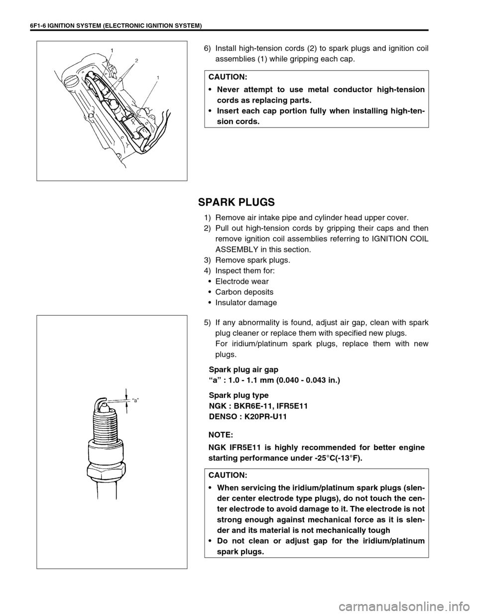
2) Disconnect high-tension cords (2) from ignition coil assem-
blies (1) while gripping each cap.
3) Pull out high-tension cords from spark plugs while gripping
each cap.
4) Measure resistance of high-tension cord (1) by using ohm-
meter.
High-tension cord resistance
: 4 -10 k
Ω/m (1.2 - 3.0 kΩ/ft)
5) If resistance exceeds specification, replace high-tension
cord(s). WARNING:
Without disconnection of injector couplers, combustible
gas may come out from spark plug holes during this test
and may get ignited in engine room.
CAUTION:
Removal of high-tension cords together with clamps
will be recommended so as not to damage their inside
wire (resistive conductor).
For the same reason, pull out each connection by grip-
ping cap portion.
Page 668 of 698

6F1-6 IGNITION SYSTEM (ELECTRONIC IGNITION SYSTEM)
6) Install high-tension cords (2) to spark plugs and ignition coil
assemblies (1) while gripping each cap.
SPARK PLUGS
1) Remove air intake pipe and cylinder head upper cover.
2) Pull out high-tension cords by gripping their caps and then
remove ignition coil assemblies referring to IGNITION COIL
ASSEMBLY in this section.
3) Remove spark plugs.
4) Inspect them for:
Electrode wear
Carbon deposits
Insulator damage
5) If any abnormality is found, adjust air gap, clean with spark
plug cleaner or replace them with specified new plugs.
For iridium/platinum spark plugs, replace them with new
plugs.
Spark plug air gap
“a” : 1.0 - 1.1 mm (0.040 - 0.043 in.)
Spark plug type
NGK : BKR6E-11, IFR5E11
DENSO : K20PR-U11 CAUTION:
Never attempt to use metal conductor high-tension
cords as replacing parts.
Insert each cap portion fully when installing high-ten-
sion cords.
NOTE:
NGK IFR5E11 is highly recommended for better engine
starting performance under -25°C(-13°F).
CAUTION:
When servicing the iridium/platinum spark plugs (slen-
der center electrode type plugs), do not touch the cen-
ter electrode to avoid damage to it. The electrode is not
strong enough against mechanical force as it is slen-
der and its material is not mechanically tough
Do not clean or adjust gap for the iridium/platinum
spark plugs.