Page 92 of 698

AIR CONDITIONING (OPTIONAL) 1B-27
ON-VEHICLE SERVICE
SERVICE PRECAUTION
When servicing air conditioning system, note the following instructions.
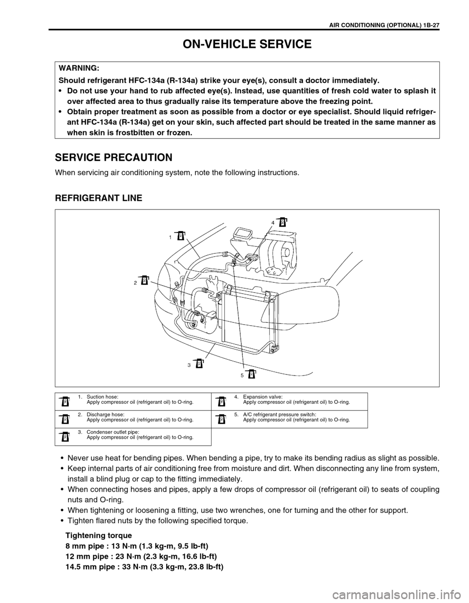
REFRIGERANT LINE
Never use heat for bending pipes. When bending a pipe, try to make its bending radius as slight as possible.
Keep internal parts of air conditioning free from moisture and dirt. When disconnecting any line from system,
install a blind plug or cap to the fitting immediately.
When connecting hoses and pipes, apply a few drops of compressor oil (refrigerant oil) to seats of coupling
nuts and O-ring.
When tightening or loosening a fitting, use two wrenches, one for turning and the other for support.
Tighten flared nuts by the following specified torque.
Tightening torque
8 mm pipe : 13 N·m (1.3 kg-m, 9.5 lb-ft)
12 mm pipe : 23 N·m (2.3 kg-m, 16.6 lb-ft)
14.5 mm pipe : 33 N·m (3.3 kg-m, 23.8 lb-ft) WARNING:
Should refrigerant HFC-134a (R-134a) strike your eye(s), consult a doctor immediately.
Do not use your hand to rub affected eye(s). Instead, use quantities of fresh cold water to splash it
over affected area to thus gradually raise its temperature above the freezing point.
Obtain proper treatment as soon as possible from a doctor or eye specialist. Should liquid refriger-
ant HFC-134a (R-134a) get on your skin, such affected part should be treated in the same manner as
when skin is frostbitten or frozen.
1. Suction hose:
Apply compressor oil (refrigerant oil) to O-ring.4. Expansion valve:
Apply compressor oil (refrigerant oil) to O-ring.
2. Discharge hose:
Apply compressor oil (refrigerant oil) to O-ring.5. A/C refrigerant pressure switch:
Apply compressor oil (refrigerant oil) to O-ring.
3. Condenser outlet pipe:
Apply compressor oil (refrigerant oil) to O-ring.
Page 97 of 698
1B-32 AIR CONDITIONING (OPTIONAL)
COOLING UNIT (EVAPORATOR)
REMOVAL
1) Disconnect negative (–) cable at battery.
2) Recover refrigerant from A/C system by referring to
“RECOVERY” in this section.
3) Remove glove box.
1. A/C evaporator 6. Dash packing 11. O-ring
2. A/C evaporator temperature sensor 7. Packing 12. Door link
3. Expansion valve 8. Fresh air duct case 13. Lower packing
4. Evaporator case
: Apply sealant 99000-31160 to hatched part “A”.9. Clamp Do not reuse.
5. Cooling unit packing 10. Air inlet door
CAUTION:
Be careful not to damage A/C evaporator fins. If A/C
evaporator fin is bent, straighten it by using flat head
screwdriver or pair of pliers.
NOTE:
The amount of removed compressor oil must be mea-
sured for replenishing compressor oil.
Page 98 of 698

AIR CONDITIONING (OPTIONAL) 1B-33
4) Remove fresh air control cable (1) and A/C evaporator tem-
perature sensor coupler.
5) Disconnect suction hose (1) and condenser outlet hose (2)
by removing attaching bolt (3).
6) Remove cooling unit mounting nuts (4) and screws (5).
7) Remove cooling unit (6).
INSPECTION
Check the following.
Clog of A/C evaporator fins.
If any clogs are found, A/C evaporator fins should be
washed with water, and should be dried with compressed
air.
A/C evaporator fins for leakage and breakage.
If any defects are found, repair or replace A/C evaporator.
A/C evaporator fittings for leakage.
If any defects are found, repair or replace A/C evaporator.
INSTALLATION
Reverse removal procedure to install cooling unit noting the fol-
lowing instructions.
If A/C evaporator temperature sensor removed, its should be
reinstalled in original position.
Replenish specified amount of compressor oil to compressor
suction side by referring to “REPLENISHING COMPRES-
SOR OIL” in this section.
Install uniformly the packing (1) to installation hole.
Evacuate and charge refrigerant by referring to “EVACUAT-
ING” and “CHARGING” in this section.
Adjust fresh air control cable, refer to “HEATER LEVER
ASSEMBLY” in Section 1A.
Page 99 of 698

1B-34 AIR CONDITIONING (OPTIONAL)
A/C EVAPORATOR TEMPERATURE SENSOR
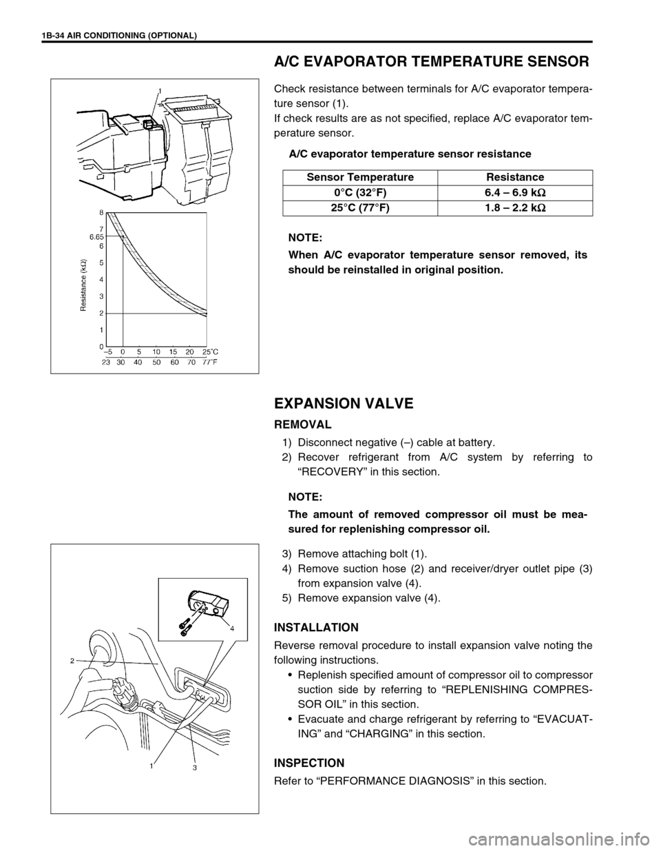
Check resistance between terminals for A/C evaporator tempera-
ture sensor (1).
If check results are as not specified, replace A/C evaporator tem-
perature sensor.
A/C evaporator temperature sensor resistance
EXPANSION VALVE
REMOVAL
1) Disconnect negative (–) cable at battery.
2) Recover refrigerant from A/C system by referring to
“RECOVERY” in this section.
3) Remove attaching bolt (1).
4) Remove suction hose (2) and receiver/dryer outlet pipe (3)
from expansion valve (4).
5) Remove expansion valve (4).
INSTALLATION
Reverse removal procedure to install expansion valve noting the
following instructions.
Replenish specified amount of compressor oil to compressor
suction side by referring to “REPLENISHING COMPRES-
SOR OIL” in this section.
Evacuate and charge refrigerant by referring to “EVACUAT-
ING” and “CHARGING” in this section.
INSPECTION
Refer to “PERFORMANCE DIAGNOSIS” in this section. Sensor Temperature Resistance
0°C (32°F) 6.4 – 6.9 k
Ω
ΩΩ Ω
25°C (77°F) 1.8 – 2.2 k
Ω
ΩΩ Ω
NOTE:
When A/C evaporator temperature sensor removed, its
should be reinstalled in original position.
NOTE:
The amount of removed compressor oil must be mea-
sured for replenishing compressor oil.
Page 399 of 698

6-30 ENGINE GENERAL INFORMATION AND DIAGNOSIS
Improper engine
idling or engine fails
to idleFaulty spark plug Spark plugs in Section 6F1.
Leaky or disconnected high-tension cord High-tension cords in Section 6F1.
Faulty ignition coil with ignitor Ignition coil in Section 6F1.
Fuel pressure out of specification Diagnostic Flow Table B-3.
Leaky manifold, throttle body, or cylinder
head gasket
Malfunctioning EGR valve (if equipped) EGR system in Section 6E1.
Faulty idle air control system Diagnostic Flow Table B-4.
Faulty evaporative emission control system EVAP control system in Section 6E1.
Faulty EGR system (if equipped) EGR system in Section 6E1.
Faulty fuel injector(s) Diagnostic Flow Table B-1.
Poor performance of ECT sensor, TP sensor
or MAP sensorECT sensor, TP sensor or MAP sensor
in Section 6E1.
Faulty ECM
Loose connection or disconnection of vacuum
hoses
Malfunctioning PCV valve PCV system in Section 6E1.
Engine overheating Refer to “Overheating” section.
Low compression Previously outlined.
Excessive hydrocar-
bon (HC) emission
or carbon monox-
ide (CO)Faulty spark plug Spark plugs in Section 6F1.
Leaky or disconnected high-tension cord High-tension cords in Section 6F1.
Faulty ignition coil with ignitor Ignition coil assembly in Section 6F1.
Low compression Refer to “Low compression” section.
Lead contamination of three way catalytic
converterCheck for absence of filler neck restric-
tor.
Faulty evaporative emission control system EVAP control system in Section 6E1.
Fuel pressure out of specification Diagnostic Flow Table B-3.
Closed loop system (A/F feed back compen-
sation) fails
Faulty TP sensor
Poor performance of ECT sensor or MAP
sensorTP sensor in Section 6E1.
ECT sensor or MAP sensor in Section
6E1.
Faulty injector(s) Diagnostic Flow Table B-1
Faulty ECM
Engine not at normal operating temperature
Clogged air cleaner
Vacuum leaks
Excessive nitrogen
oxides (NOx) emis-
sionImproper ignition timing See section 6F1.
Lead contamination of catalytic converter Check for absence of filler neck restric-
tor.
Faulty EGR system (if equipped) EGR system in Section 6E1.
Fuel pressure out of specification Diagnostic Flow Table B-3.
Closed loop system (A/F feed back compen-
sation) fails
Faulty TP sensor
Poor performance of ECT sensor or MAP
sensorTP sensor in Section 6E1.
ECT sensor or MAP sensor in Section
6E1.
Faulty injector(s) Diagnostic Flow Table B-1
Faulty ECM Condition Possible Cause Correction
Page 412 of 698

ENGINE GENERAL INFORMATION AND DIAGNOSIS 6-43
Resistance Check
1) Disconnect ECM couplers from ECM with ignition switch
OFF.
2) Check resistance between each terminal of connectors dis-
connected.
TERMINAL RESISTANCE TABLE
For TYPE A (Refer to NOTE in “ECM VOLTAGE VALUES TABLE” for applicable model) CAUTION:
Never touch terminals of ECM itself or connect voltmeter
or ohmmeter.
CAUTION:
Be sure to connect ohmmeter probe from wire harness
side of coupler.
Be sure to turn OFF ignition switch for this check.
Resistance in table below represents that when parts
temperature is 20°C (68°F).
1. ECM coupler disconnected
2. Ohmmeter
TERMINALS CIRCUIT STANDARD
RESISTANCE
C42-7 to G02-6 HO2S-1 heater (if equipped) 5.0 – 6.4 Ω
C41-4 to G02-6 HO2S-2 heater (if equipped) 12.0 – 14.3 Ω
C42-9 to C41-5/6 No.1 injector 11.3 – 13.8 Ω
C42-21 to C41-5/6 No.2 injector 11.3 – 13.8 Ω
C42-31 to C41-5/6 No.3 injector 11.3 – 13.8 Ω
C42-8 to C41-5/6 No.4 injector 11.3 – 13.8 Ω
C41-2 to C41-5/6 EGR valve (stepper motor coil 1) (if equipped) 20 – 24 Ω
C41-9 to C41-5/6 EGR valve (stepper motor coil 2) (if equipped) 20 – 24 Ω
C41-8 to C41-5/6 EGR valve (stepper motor coil 3) (if equipped) 20 – 24 Ω
C41-17 to C41-5/6 EGR valve (stepper motor coil 4) (if equipped) 20 – 24 Ω
C42-4 to C41-5/6 EVAP canister purge valve 30 – 34 Ω
C41-19 to G02-6 Fuel pump relay 56 – 146 Ω
C41-1 to Body ground A/C compressor clutch 3 – 5.5 Ω
C41-18 to C41-5/6 Radiator fan control relay No.1 56 – 146 Ω
C41-10 to G02-17 Main relay 56 – 146 Ω
C42-1 to Body ground Ground Continuity
C42-2 to Body ground Ground Continuity
C42-3 to Body ground Ground Continuity
Page 505 of 698
6A1-4 ENGINE MECHANICAL (M13 ENGINE)
DIAGNOSIS
DIAGNOSIS TABLE
Refer to “ENGINE MECHANICAL DIAGNOSIS TABLE” in Sec-
tion 6.
COMPRESSION CHECK
Check compression pressure on all 4 cylinders as follows:
1) Warm up engine to normal operating temperature.
2) Stop engine after warming up.
3) Remove air cleaner assembly (1), resonator (2) and hoses.
Refer to “AIR CLEANER ASSEMBLY AND RESONATOR”.
4) Remove cylinder head upper cover (1).
5) Disconnect ignition coil couplers (1).
6) Remove ignition coil assemblies (2) with high-tension cord
(3).
7) Remove all spark plugs.
8) Disconnect fuel injector wires (4) at the coupler.NOTE:
After warming up engine, place transmission gear shift
lever in “Neutral” (shift selector lever to “P” range for A/T
model), and set parking brake and block drive wheels.
Page 507 of 698

6A1-6 ENGINE MECHANICAL (M13 ENGINE)
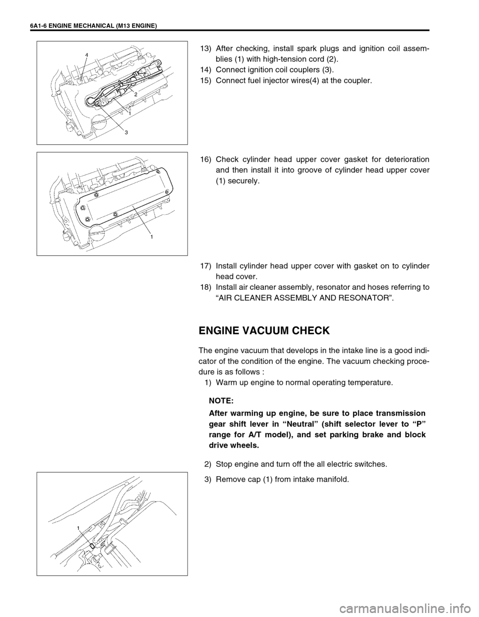
13) After checking, install spark plugs and ignition coil assem-
blies (1) with high-tension cord (2).
14) Connect ignition coil couplers (3).
15) Connect fuel injector wires(4) at the coupler.
16) Check cylinder head upper cover gasket for deterioration
and then install it into groove of cylinder head upper cover
(1) securely.
17) Install cylinder head upper cover with gasket on to cylinder
head cover.
18) Install air cleaner assembly, resonator and hoses referring to
“AIR CLEANER ASSEMBLY AND RESONATOR”.
ENGINE VACUUM CHECK
The engine vacuum that develops in the intake line is a good indi-
cator of the condition of the engine. The vacuum checking proce-
dure is as follows :
1) Warm up engine to normal operating temperature.
2) Stop engine and turn off the all electric switches.
3) Remove cap (1) from intake manifold.
NOTE:
After warming up engine, be sure to place transmission
gear shift lever in “Neutral” (shift selector lever to “P”
range for A/T model), and set parking brake and block
drive wheels.