Page 426 of 698

ENGINE GENERAL INFORMATION AND DIAGNOSIS 6-57
Fig. 3 for Step 4
DTC P0115 (DTC NO.19) ENGINE COOLANT TEMPERATURE (ECT) CIRCUIT
MALFUNCTION
WIRING DIAGRAM / CIRCUIT DESCRIPTION
C42-14
5V
ECM
LT GRN
ORN
YEL/GRN
C42-10
C42 (31P) C41 (24P) G02 (17P)1 2 3 4 5 6 7 8 9
10 11 12 13 14 15 16 17 18 19 20 21
22 23 24 25 26 28 27 29 30 315 6
1 2 3 4 5 6 7
11 12
9 10 11 13 12 14 15 16
16 171 2
7 8
13 14 3 4
9 10
15 17 188
19 20 21 22 23 24
DTC DETECTING CONDITION POSSIBLE CAUSE
Low engine coolant temperature (High voltage-High resis-
tance)
or
High engine coolant temperature (Low voltage-Low resis-
tance)“LT GRN” circuit open or shorted to power
“ORN” circuit open
ECT sensor malfunction
ECM malfunction
NOTE:
Before inspecting, be sure to check that coolant temp. meter in combination meter indicates normal
operating temperature (Engine is not overheating).
When this DTC and P1709 are stored together, also clear DTC stored in TCM after completion of
repair.
When DTC P0105 (No.11), P0110 (No.18), P0115 (No.19) and P0120 (No.13) are indicated together, it
is possible that “ORN” circuit open.
Page 451 of 698

6-82 ENGINE GENERAL INFORMATION AND DIAGNOSIS
DTC CONFIRMATION PROCEDURE
1) Turn ignition switch OFF.
2) Clear DTC with ignition switch ON.
3) Check vehicle and environmental condition for :
–Altitude (barometric pressure) : 2400 m, 8000 ft or less (560 mmHg, 75 kPa or more)
–Ambient temp. : –10°C, 14°F or higher
–Intake air temp. : 70°C, 158°F or lower
–Engine coolant temp. : – 10 – 110°C, 14 – 230°F
4) Start engine and keep it at idle for 2 min. or more.
5) Check DTC in “DTC” mode and pending DTC in “ON BOARD TEST” or “PENDING DTC” mode.
6) If DTC is not detected at idle, consult usual driving based on information obtained in “Customer complaint
analysis” and “Freeze frame data check”.
INSPECTION
DTC DETECTING CONDITION POSSIBLE CAUSE
Engine under other than high revolution condition
Not on rough road
Engine speed changing rate (Below specified value)
Manifold absolute pressure changing rate (Below
specified value)
Throttle opening changing rate (Below specified
value)
Misfire rate per 200 or 1000 engine revolutions (how
much and how often crankshaft revolution speed
changes) is higher than specified valueEngine overheating
Vacuum leaks (air inhaling) from air intake system
Ignition system malfunction (spark plug(s), high-
tension cord(s), ignition coil assembly)
Fuel pressure out of specification
Fuel injector malfunction (clogged or leakage)
Engine compression out of specification
Valve lash (clearance) out of specification
Manifold absolute pressure sensor malfunction
Engine coolant temp. sensor malfunction
PCV valve malfunction
EVAP control system malfunction
EGR system malfunction
NOTE:
Among different types of random misfire, if misfire occurs at cylinders 1 and 4 or cylinders 3 and 2
simultaneously, it may not possible to reconfirm DTC by using the following DTC confirmation proce-
dure. When diagnosing the trouble of DTC P0300 (Random misfire detected) of the engine which is
apparently misfiring, even if DTC P0300 cannot be reconfirmed by using the following DTC confirma-
tion procedure, proceed to the following Diag. Flow Table.
WARNING:
When performing a road test, select a place where there is no traffic or possibility of a traffic acci-
dent and be very careful during testing to avoid occurrence of an accident.
Road test should be carried out with 2 persons, a driver and a tester.
CAUTION:
For iridium spark plugs, do not adjust air gap or clean.
Step Action Yes No
1Was “ENGINE DIAG. FLOW TABLE” performed? Go to Step 2. Go to “ENGINE
DIAG. FLOW
TABLE”.
Page 602 of 698

ENGINE COOLING 6B-13
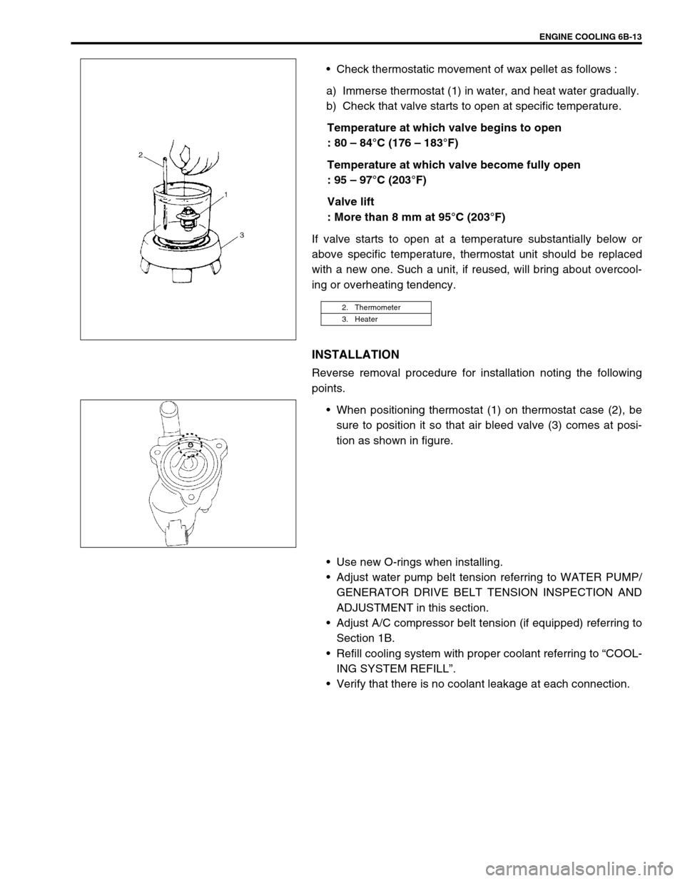
Check thermostatic movement of wax pellet as follows :
a) Immerse thermostat (1) in water, and heat water gradually.
b) Check that valve starts to open at specific temperature.
Temperature at which valve begins to open
: 80 – 84°C (176 – 183°F)
Temperature at which valve become fully open
: 95 – 97°C (203°F)
Valve lift
: More than 8 mm at 95°C (203°F)
If valve starts to open at a temperature substantially below or
above specific temperature, thermostat unit should be replaced
with a new one. Such a unit, if reused, will bring about overcool-
ing or overheating tendency.
INSTALLATION
Reverse removal procedure for installation noting the following
points.
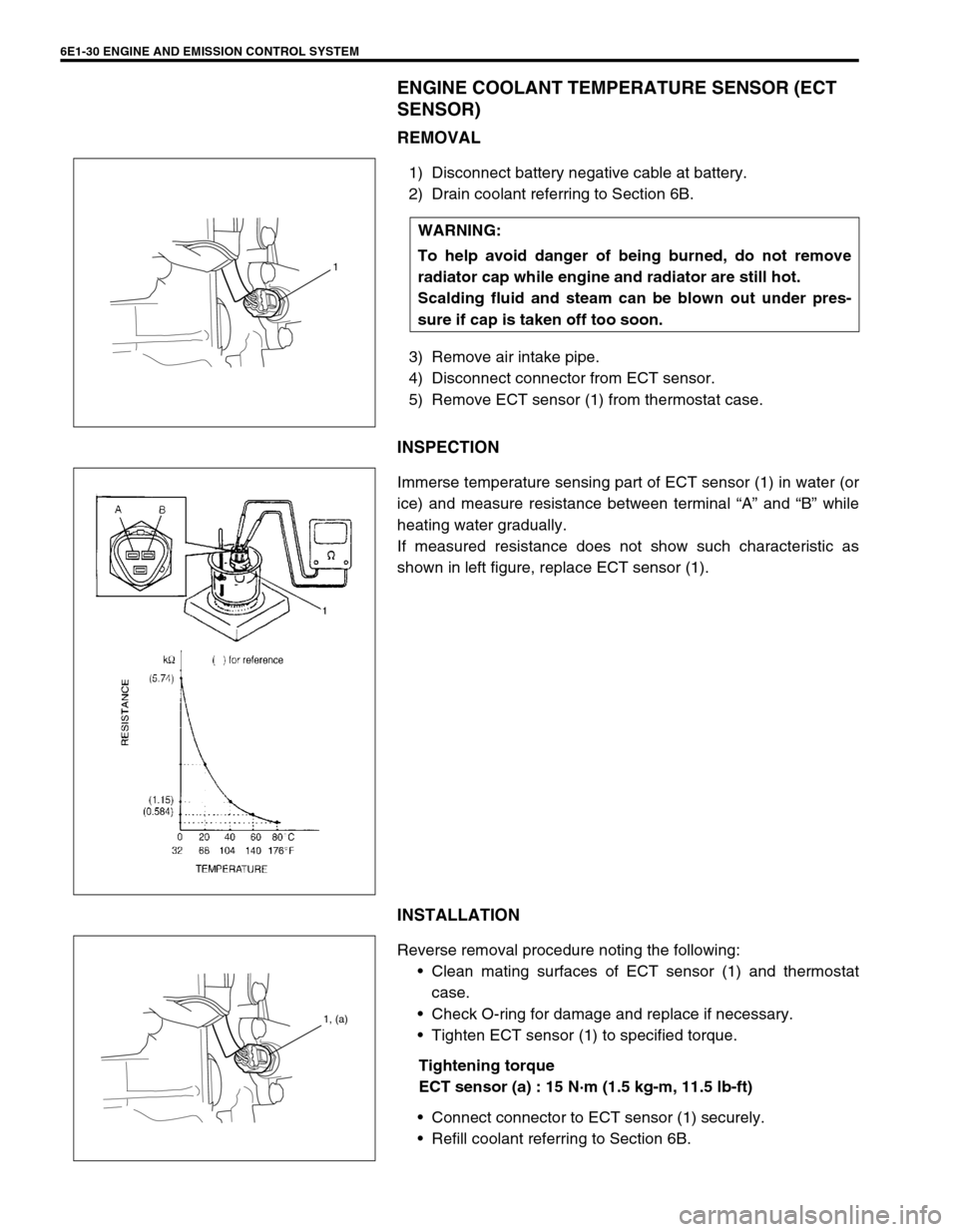
When positioning thermostat (1) on thermostat case (2), be
sure to position it so that air bleed valve (3) comes at posi-
tion as shown in figure.
Use new O-rings when installing.
Adjust water pump belt tension referring to WATER PUMP/
GENERATOR DRIVE BELT TENSION INSPECTION AND
ADJUSTMENT in this section.
Adjust A/C compressor belt tension (if equipped) referring to
Section 1B.
Refill cooling system with proper coolant referring to “COOL-
ING SYSTEM REFILL”.
Verify that there is no coolant leakage at each connection.
2. Thermometer
3. Heater
Page 650 of 698
ENGINE AND EMISSION CONTROL SYSTEM 6E1-29
INTAKE AIR TEMPERATURE SENSOR (IAT SENSOR)
REMOVAL
1) Disconnect battery negative cable at battery.
2) Disconnect coupler (1) from IAT sensor.
3) Remove IAT sensor from air cleaner case (2).
INSPECTION
Immerse temperature sensing part of IAT sensor in water (or ice)
and measure resistance between sensor terminals while heating
water gradually.
If measured resistance does not show such characteristic as
shown in left figure, replace IAT sensor.
INSTALLATION
Reverse removal procedure noting the following.
Clean mating surfaces of IAT sensor and air cleaner case.
Connect IAT sensor connector (1) securely.
1
2
1
Page 651 of 698

6E1-30 ENGINE AND EMISSION CONTROL SYSTEM
ENGINE COOLANT TEMPERATURE SENSOR (ECT
SENSOR)
REMOVAL
1) Disconnect battery negative cable at battery.
2) Drain coolant referring to Section 6B.
3) Remove air intake pipe.
4) Disconnect connector from ECT sensor.
5) Remove ECT sensor (1) from thermostat case.
INSPECTION
Immerse temperature sensing part of ECT sensor (1) in water (or
ice) and measure resistance between terminal “A” and “B” while
heating water gradually.
If measured resistance does not show such characteristic as
shown in left figure, replace ECT sensor (1).
INSTALLATION
Reverse removal procedure noting the following:
Clean mating surfaces of ECT sensor (1) and thermostat
case.
Check O-ring for damage and replace if necessary.
Tighten ECT sensor (1) to specified torque.
Tightening torque
ECT sensor (a) : 15 N·m (1.5 kg-m, 11.5 lb-ft)
Connect connector to ECT sensor (1) securely.
Refill coolant referring to Section 6B. WARNING:
To help avoid danger of being burned, do not remove
radiator cap while engine and radiator are still hot.
Scalding fluid and steam can be blown out under pres-
sure if cap is taken off too soon.
1
1, (a)
Page 696 of 698

6K-2 EXHAUST SYSTEM
GENERAL DESCRIPTION
The exhaust system consists of an exhaust manifold, three-way catalytic converter (TWC) in catalyst case,
exhaust pipes, a muffler and seals, gasket and etc.
The three-way catalytic converter is an emission control device added to the exhaust system to lower the levels
of Hydrocarbon (HC), Carbon Monoxide (CO), and Oxides of Nitrogen (NOx) pollutants in the exhaust gas.
MAINTENANCE
At every interval of periodic maintenance service, and when vehi-
cle is raised for other service, check exhaust system as follows:
Check rubber mountings for damage, deterioration, and out
of position.
Check exhaust system for leakage, loose connection, dent
and damage.
If bolts or nuts are loosened, tighten them to specified
torque.
Refer to “GENERAL DESCRIPTION”.
Check nearby body areas damaged, missing, or misposi-
tioned part, open seam, hole connection or any other defect
which could permit exhaust fumes to seep into vehicle.
Make sure that exhaust system components have enough
clearance from underbody to avoid overheating and possible
damage to passenger compartment carpet.
Any defect should be fixed at once. WARNING:
To avoid the danger of being burned, do not touch the
exhaust system when the system is hot. Any service on
the exhaust system should be performed when the sys-
tem is cool.