Page 527 of 698
6A1-26 ENGINE MECHANICAL (M13 ENGINE)
3) Remove right side engine under cover (1).
4) Remove A/C compressor belt (3) (if equipped).
5) Remove water pump belt (1).
6) Remove water pump pulley (2).
7) Drain engine oil.
8) Remove crankshaft pulley bolt (2).
To lock crankshaft pulley (1), use special tool with it as
shown in figure.
Special tool
(A) : 09917-68221
9) Remove oil pan (1) referring to “OIL PAN AND OIL PUMP
STRAINER”.
10) Remove cylinder head cover referring to “CYLINDER HEAD
COVER”.
Page 535 of 698

6A1-34 ENGINE MECHANICAL (M13 ENGINE)
TIMING CHAIN AND CHAIN TENSIONER
REMOVAL
1) Disconnect negative cable at battery.
2) Drain engine oil.
3) Remove oil pan referring to “OIL PAN AND OIL PUMP
STRAINER”.
4) Remove cylinder head cover referring to “CYLINDER HEAD
COVER”.
5) Remove timing chain cover referring to “TIMING CHAIN
COVER”.
6) Align both intake and exhaust camshaft timing sprocket
marks (1) with notches (2) of cylinder head respectively by
turning crankshaft.
7) Remove timing chain tensioner adjuster assembly (3).
8) Remove timing chain tensioner (4).
9) Remove timing chain No.1 guide (5).
10) Remove timing chain (6) with crankshaft timing sprocket (7).
1. Crankshaft timing sprocket 4. Timing chain tensioner
: Apply engine oil to sliding surface.7. Chain tensioner mounting bolt
2. Timing chain
: Apply engine oil.5. Timing chain tensioner adjuster assembly 8. Chain guide mounting bolt
3. Timing chain No.1 guide
: Apply engine oil to sliding surface.6. Chain tensioner adjuster mounting bolt Tightening torque
CAUTION:
After timing chain is removed, never turn crankshaft and
camshafts independently more than its allowable turning
range described in “INSTALLATION” section.
If turned, interference may occur between piston and
valves and valves themselves, and parts related to piston
and valves may be damaged.
Page 545 of 698
6A1-44 ENGINE MECHANICAL (M13 ENGINE)
VALVES AND CYLINDER HEAD
REMOVAL
1) Relieve fuel pressure according to procedure described in
Section 6.
2) Disconnect negative cable at battery.
3) Drain engine oil.
[A]✱1) Tighten all bolts at 40 N·m (4.0 kg-m)
2) Turn all bolts at 60°
3) Then, Turn all bolt at 60° once again6. Intake valve 12. Knock pin
1. Valve cotters 7. Exhaust valve
Tightening torque
2. Valve spring retainer 8. Valve guide
Do not reuse.
3. Valve spring 9. Cylinder head bolt
: Never reuse it due to plastic deformation
tightening bolt.Apply engine oil to sliding surface of
each part.
4. Valve stem seal 10. Cylinder head
5. Valve spring seat 11. Cylinder head gasket
: “TOP” mark provided on gasket comes to
crankshaft pulley side, facing up.
Page 558 of 698

ENGINE MECHANICAL (M13 ENGINE) 6A1-57
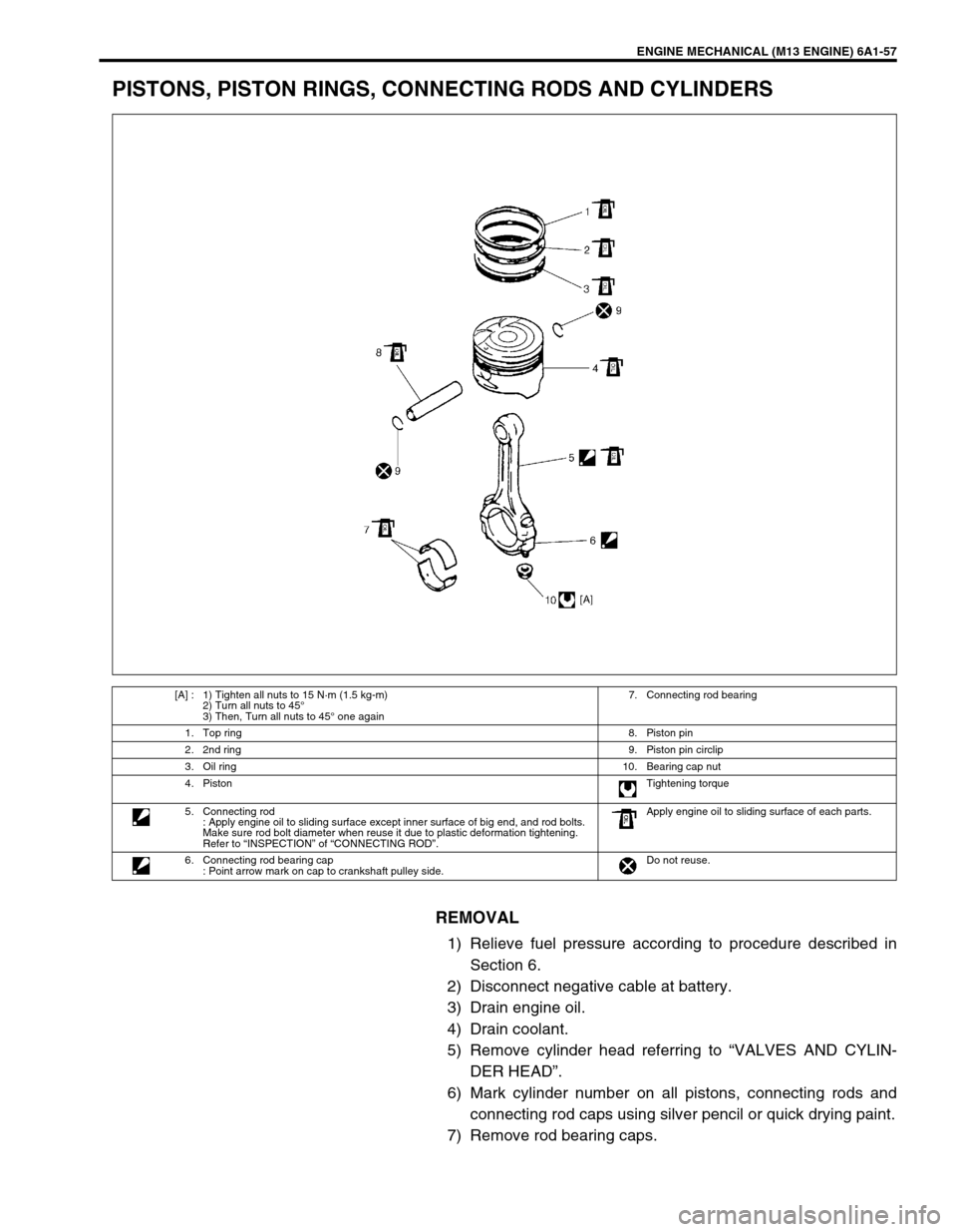
PISTONS, PISTON RINGS, CONNECTING RODS AND CYLINDERS
REMOVAL
1) Relieve fuel pressure according to procedure described in
Section 6.
2) Disconnect negative cable at battery.
3) Drain engine oil.
4) Drain coolant.
5) Remove cylinder head referring to “VALVES AND CYLIN-
DER HEAD”.
6) Mark cylinder number on all pistons, connecting rods and
connecting rod caps using silver pencil or quick drying paint.
7) Remove rod bearing caps.
[A] : 1) Tighten all nuts to 15 N·m (1.5 kg-m)
2) Turn all nuts to 45°
3) Then, Turn all nuts to 45° one again7. Connecting rod bearing
1. Top ring8. Piston pin
2. 2nd ring9. Piston pin circlip
3. Oil ring10. Bearing cap nut
4. PistonTightening torque
5. Connecting rod
: Apply engine oil to sliding surface except inner surface of big end, and rod bolts.
Make sure rod bolt diameter when reuse it due to plastic deformation tightening.
Refer to “INSPECTION” of “CONNECTING ROD”.Apply engine oil to sliding surface of each parts.
6. Connecting rod bearing cap
: Point arrow mark on cap to crankshaft pulley side.Do not reuse.
Page 587 of 698

6A1-86 ENGINE MECHANICAL (M13 ENGINE)
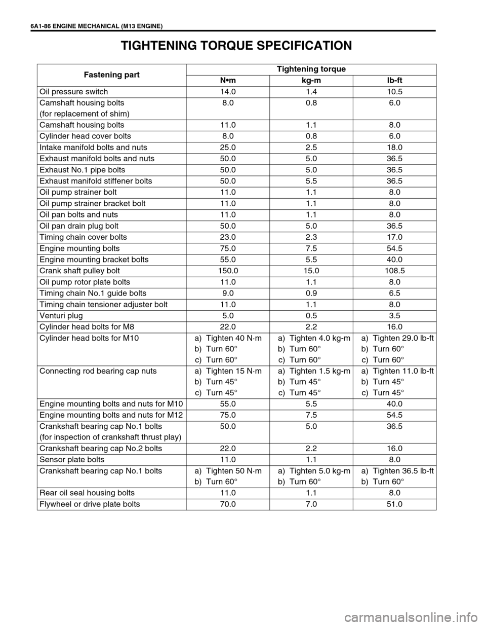
TIGHTENING TORQUE SPECIFICATION
Fastening partTightening torque
Nm kg-m lb-ft
Oil pressure switch 14.0 1.4 10.5
Camshaft housing bolts
(for replacement of shim)8.0 0.8 6.0
Camshaft housing bolts 11.0 1.1 8.0
Cylinder head cover bolts 8.0 0.8 6.0
Intake manifold bolts and nuts 25.0 2.5 18.0
Exhaust manifold bolts and nuts 50.0 5.0 36.5
Exhaust No.1 pipe bolts 50.0 5.0 36.5
Exhaust manifold stiffener bolts 50.0 5.5 36.5
Oil pump strainer bolt 11.0 1.1 8.0
Oil pump strainer bracket bolt 11.0 1.1 8.0
Oil pan bolts and nuts 11.0 1.1 8.0
Oil pan drain plug bolt 50.0 5.0 36.5
Timing chain cover bolts 23.0 2.3 17.0
Engine mounting bolts 75.0 7.5 54.5
Engine mounting bracket bolts 55.0 5.5 40.0
Crank shaft pulley bolt 150.0 15.0 108.5
Oil pump rotor plate bolts 11.0 1.1 8.0
Timing chain No.1 guide bolts 9.0 0.9 6.5
Timing chain tensioner adjuster bolt 11.0 1.1 8.0
Venturi plug 5.0 0.5 3.5
Cylinder head bolts for M8 22.0 2.2 16.0
Cylinder head bolts for M10 a) Tighten 40 N·m
b) Turn 60°
c) Turn 60°a) Tighten 4.0 kg-m
b) Turn 60°
c) Turn 60°a) Tighten 29.0 lb-ft
b) Turn 60°
c) Turn 60°
Connecting rod bearing cap nuts a) Tighten 15 N·m
b) Turn 45°
c) Turn 45°a) Tighten 1.5 kg-m
b) Turn 45°
c) Turn 45°a) Tighten 11.0 lb-ft
b) Turn 45°
c) Turn 45°
Engine mounting bolts and nuts for M10 55.0 5.5 40.0
Engine mounting bolts and nuts for M12 75.0 7.5 54.5
Crankshaft bearing cap No.1 bolts
(for inspection of crankshaft thrust play)50.0 5.0 36.5
Crankshaft bearing cap No.2 bolts 22.0 2.2 16.0
Sensor plate bolts 11.0 1.1 8.0
Crankshaft bearing cap No.1 bolts a) Tighten 50 N·m
b) Turn 60°a) Tighten 5.0 kg-m
b) Turn 60°a) Tighten 36.5 lb-ft
b) Turn 60°
Rear oil seal housing bolts 11.0 1.1 8.0
Flywheel or drive plate bolts 70.0 7.0 51.0
Page 599 of 698
6B-10 ENGINE COOLING
ON-VEHICLE SERVICE
SYSTEM COMPONENTS
WARNING:
Check to make sure that engine coolant temperature is cold before removing any part of cooling
system.
Also be sure to disconnect negative cord from battery terminal before removing any part.
1. Radiator 11. To throttle body 21. To timing chain cover
2. Reservoir tank 12. To heater unit 22. O-Ring
3. Radiator cap 13. To water pump 23. Gasket
4. Drain plug 14. Radiator and condenser cooling fan assembly 24. Water outlet cap O-ring No.1
5. Radiator outlet hose 15. Water inlet pipe No.1 25. Water outlet cap O-ring No.2
6. Radiator inlet hose 16. Water inlet pipe No.2 26. Thermostat cap bolts
7. Thermostat 17. Thermostat cap 27. Thermostat case bolts
8. ECT sensor 18. Water outlet cap Tightening torque
9. Thermostat case 19. Heater inlet hose Do not reuse.
10. To cylinder head 20. Heater outlet hose
Page 605 of 698

6B-16 ENGINE COOLING
INSTALLATION
1) Install belt (1) to water pump pulley (2), crankshaft pulley (3)
and generator pulley (4).
When servicing car equipped with A/C, install compressor
drive belt, too.
2) Adjust belt tension by referring to “WATER PUMP/GENERA-
TOR DRIVE BELT TENSION INSPECTION AND ADJUST-
MENT” in this section.
For adjustment of compressor drive belt tension, refer to
COMPRESSOR DRIVE BELT in Section 1B.
3) Tighten water pump belt adjusting bolt and pivot bolt to spec-
ified torque.
Tightening torque
Generator adjusting bolt (a) : 23 N·m (2.3 kg-m, 17.0 lb-ft)
Generator pivot bolt (b) : 50 N·m (5.0 kg-m, 36.0 lb-ft)
4) Connect negative cable at battery.
WATER PUMP BELT TENSION INSPECTION AND
ADJUSTMENT
For this inspection or adjustment, refer to “WATER PUMP GEN-
ERATOR DRIVE BELT TENSION INSPECTION AND ADJUST-
MENT”.
WATER PUMP
REMOVAL
1) Disconnect negative cable at battery.
2) Drain coolant. Refer to “COOLING SYSTEM DRAINING”.
3) Remove A/C compressor belt (4) by referring to “COM-
PRESSOR DRIVE BELT” in Section 1B. (if equipped).
4) Loosen water pump/generator drive belt adjusting bolt (1)
and generator pivot bolt (2). Then remove water pump/gen-
erator drive belt (3) and water pump pulley.
Refer to “WATER PUMP BELT” in this section.
2
1
3
4
1
2
43
Page 616 of 698

ENGINE FUEL 6C-9
FUEL TANK PURGING PROCEDURE
The following procedure is used for purging fuel tank.
1) After removing fuel tank, remove all hoses, pipes, fuel pump
assembly from fuel tank.
2) Drain all remaining fuel from tank.
3) Move tank to flushing area.
4) Fill tank with warm water or tap water, and agitate vigorously
and drain. Repeat this washing until inside of tank is clean.
Replace tank if its inside is rusty.
5) Completely flush out remaining water after washing.
INSTALLATION
1) If parts have been removed from fuel tank, install them
before installing fuel tank to vehicle.
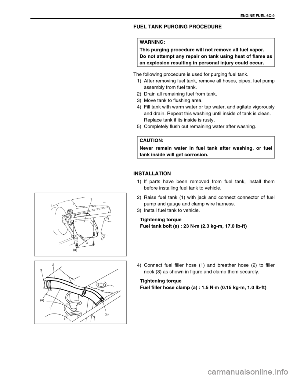
2) Raise fuel tank (1) with jack and connect connector of fuel
pump and gauge and clamp wire harness.
3) Install fuel tank to vehicle.
Tightening torque
Fuel tank bolt (a) : 23 N·m (2.3 kg-m, 17.0 lb-ft)
4) Connect fuel filler hose (1) and breather hose (2) to filler
neck (3) as shown in figure and clamp them securely.
Tightening torque
Fuel filler hose clamp (a) : 1.5 N·m (0.15 kg-m, 1.0 lb-ft) WARNING:
This purging procedure will not remove all fuel vapor.
Do not attempt any repair on tank using heat of flame as
an explosion resulting in personal injury could occur.
CAUTION:
Never remain water in fuel tank after washing, or fuel
tank inside will get corrosion.
(a) (a)
1 32