2000 SUZUKI SWIFT charging
[x] Cancel search: chargingPage 89 of 698
1B-24 AIR CONDITIONING (OPTIONAL)
CHARGING
CHARGING PROCEDURE
The initial charging of the A/C system is performed from the high
pressure side with the engine stopped.
And next, this method must be followed by charging from the low
pressure side with the engine running.
1) Check to make sure that hoses are routed properly after
evacuating the system.
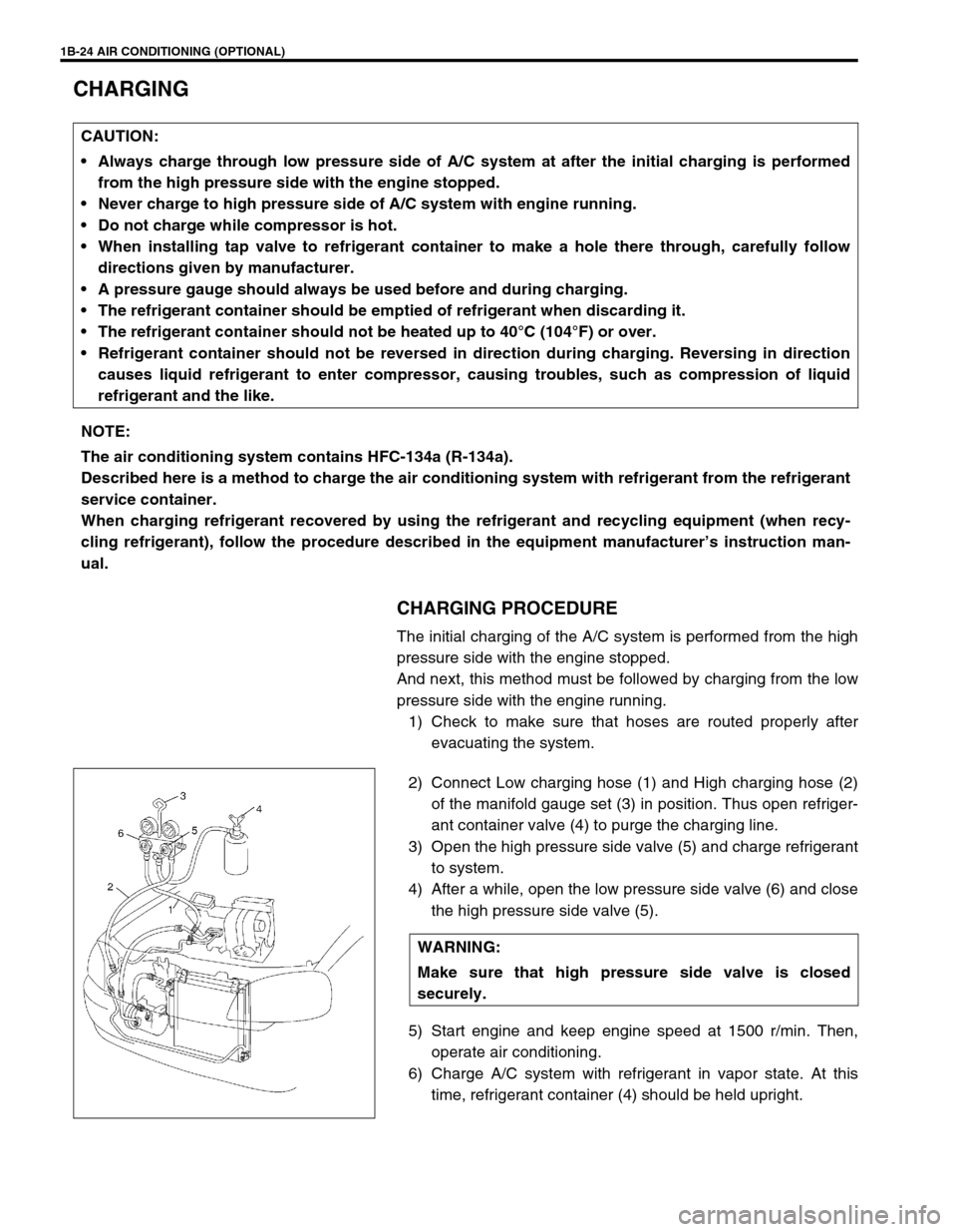
2) Connect Low charging hose (1) and High charging hose (2)
of the manifold gauge set (3) in position. Thus open refriger-
ant container valve (4) to purge the charging line.
3) Open the high pressure side valve (5) and charge refrigerant
to system.
4) After a while, open the low pressure side valve (6) and close
the high pressure side valve (5).
5) Start engine and keep engine speed at 1500 r/min. Then,
operate air conditioning.
6) Charge A/C system with refrigerant in vapor state. At this
time, refrigerant container (4) should be held upright. CAUTION:
Always charge through low pressure side of A/C system at after the initial charging is performed
from the high pressure side with the engine stopped.
Never charge to high pressure side of A/C system with engine running.
Do not charge while compressor is hot.
When installing tap valve to refrigerant container to make a hole there through, carefully follow
directions given by manufacturer.
A pressure gauge should always be used before and during charging.
The refrigerant container should be emptied of refrigerant when discarding it.
The refrigerant container should not be heated up to 40°C (104°F) or over.
Refrigerant container should not be reversed in direction during charging. Reversing in direction
causes liquid refrigerant to enter compressor, causing troubles, such as compression of liquid
refrigerant and the like.
NOTE:
The air conditioning system contains HFC-134a (R-134a).
Described here is a method to charge the air conditioning system with refrigerant from the refrigerant
service container.
When charging refrigerant recovered by using the refrigerant and recycling equipment (when recy-
cling refrigerant), follow the procedure described in the equipment manufacturer’s instruction man-
ual.
WARNING:
Make sure that high pressure side valve is closed
securely.
Page 90 of 698
AIR CONDITIONING (OPTIONAL) 1B-25
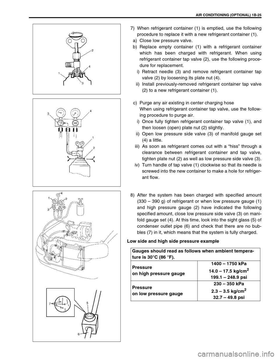
7) When refrigerant container (1) is emptied, use the following
procedure to replace it with a new refrigerant container (1).
a) Close low pressure valve.
b) Replace empty container (1) with a refrigerant container
which has been charged with refrigerant. When using
refrigerant container tap valve (2), use the following proce-
dure for replacement.
i) Retract needle (3) and remove refrigerant container tap
valve (2) by loosening its plate nut (4).
ii) Install previously-removed refrigerant container tap valve
(2) to a new refrigerant container (1).
c) Purge any air existing in center charging hose
When using refrigerant container tap valve, use the follow-
ing procedure to purge air.
i) Once fully tighten refrigerant container tap valve (1), and
then loosen (open) plate nut (2) slightly.
ii) Open low pressure side valve (3) of manifold gauge set
(4) a little.
iii) As soon as refrigerant comes out with a “hiss” through a
clearance between refrigerant container and tap valve,
tighten plate nut (2) as well as low pressure side valve (3).
iv) Turn handle of tap valve (1) clockwise so that its needle is
screwed into the new container to make a hole for refriger-
ant flow.
8) After the system has been charged with specified amount
(330 – 390 g) of refrigerant or when low pressure gauge (1)
and high pressure gauge (2) have indicated the following
specified amount, close low pressure side valve (3) on mani-
fold gauge set (4). At this time, look into the sight glass (5) of
condenser outlet pipe (6) and check that there are no bub-
bles (7) in it, which means that the system is fully charged.
Low side and high side pressure example
Gauges should read as follows when ambient tempera-
ture is 30°C (86 °F).
Pressure
on high pressure gauge1400 – 1750 kPa
14.0 – 17.5 kg/cm
2
199.1 – 248.9 psi
Pressure
on low pressure gauge230 – 350 kPa
2.3 – 3.5 kg/cm
2
32.7 – 49.8 psi
Page 91 of 698
1B-26 AIR CONDITIONING (OPTIONAL)
REMOVING MANIFOLD GAUGE SET
When A/C system has been charged with a specified amount of refrigerant, remove manifold gauge set as fol-
lows :
1) Close low pressure side valve of manifold gauge set. (The high pressure side valve is closed continuously
during the process of charging.)
2) Close refrigerant container valve.
3) Stop engine.
4) Using shop rag, remove charging hoses from service valves. This operation must be performed rapidly.
5) Put caps on service valves.
LEAK TEST
Whenever a refrigerant leak is suspected in the system or any
service operation has been performed which may result in dis-
turbing lines or connections, it is advisable to test for leaks.
Common sense should be used in performing any refrigerant leak
test, since the need and extent of any such test will, in general,
depend upon the nature of a complaint and the type of a service
performed on the system.
LIQUID LEAK DETECTORS
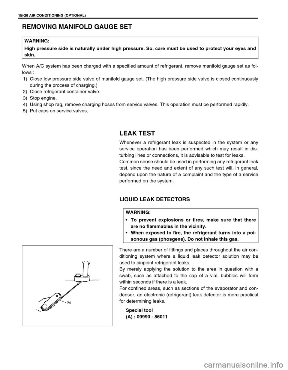
There are a number of fittings and places throughout the air con-
ditioning system where a liquid leak detector solution may be
used to pinpoint refrigerant leaks.
By merely applying the solution to the area in question with a
swab, such as attached to the cap of a vial, bubbles will form
within seconds if there is a leak.
For confined areas, such as sections of the evaporator and con-
denser, an electronic (refrigerant) leak detector is more practical
for determining leaks.
Special tool
(A) : 09990 - 86011 WARNING:
High pressure side is naturally under high pressure. So, care must be used to protect your eyes and
skin.
WARNING:
To prevent explosions or fires, make sure that there
are no flammables in the vicinity.
When exposed to fire, the refrigerant turns into a poi-
sonous gas (phosgene). Do not inhale this gas.
Page 93 of 698

1B-28 AIR CONDITIONING (OPTIONAL)
Route drain hose so that drained water does not make any contact to vehicle components.
If pipes or hoses are replaced, replenish specified amount of compressor oil to compressor suction side by
referring to “REPLENISHING COMPRESSOR OIL” in this section.
HANDLING REFRIGERANT HFC-134a (R-134a)
Always wear goggles to protect your eyes.
Avoid you direct contact to liquid refrigerant.
Do not heat refrigerant container higher than 40°C (104°F).
Do not discharge refrigerant into atmosphere.
Do not allow liquid refrigerant to touch bright metals. Refrigerant combined with moisture is corrosive and
will tarnish surfaces of bright metals including chrome.
REFRIGERANT RECOVERY
When discharging refrigerant out of A/C system, always recover it by using refrigerant recovery and recycling
equipment. Discharging refrigerant HFC-134a (R-134a) into atmosphere would cause adverse effect to environ-
ments.
REFRIGERANT CHARGE
After perform replenishing compressor oil and evacuating, charge a proper amount of refrigerant to A/C system
referring to “CHARGING” in this section.
CONDENSER ASSEMBLY
INSPECTION
Check the following.
Clog of condenser fins.
If, any clogs are found, condenser fins should be washed
with water, and should be dried with compressed air.
Condenser fins for leakage and breakage.
If any defects are found, repair or replace condenser.
Condenser fittings for leakage.
If any defects are found, repair or replace condenser. CAUTION:
Do not perform an additional refrigerant charging to A/C system. This cause it to overcharge.
CAUTION:
Be careful not to damage condenser fins. If condenser fin
is bent, straighten it by using flat head screwdriver or
pair of pliers.
Page 94 of 698

AIR CONDITIONING (OPTIONAL) 1B-29
REMOVAL
1) Disconnect negative (–) cable at battery.
2) Recover refrigerant from A/C system by referring to
“RECOVERY” in this section.
3) Remove front bumper referring to “FRONT BUMPER” in
Section 8.
4) Remove front cross member cover (1) and engine food
cover (2) from vehicle body.
5) Disconnect discharge hose (1) and condenser outlet pipe (2)
from condenser (3).
6) Remove condenser mounting bolts (4).
7) Remove condenser (3).
INSTALLATION
Reverse removal procedure to install condenser noting the follow-
ing instructions.
Replenish specified amount of compressor oil to compressor
suction side by referring to “REPLENISHING COMPRES-
SOR OIL” in this section.
Evacuate and charge refrigerant by referring to “EVACUAT-
ING” and “CHARGING” in this section. NOTE:
The amount of removed compressor oil must be mea-
sured for replenishing compressor oil.
Page 98 of 698

AIR CONDITIONING (OPTIONAL) 1B-33
4) Remove fresh air control cable (1) and A/C evaporator tem-
perature sensor coupler.
5) Disconnect suction hose (1) and condenser outlet hose (2)
by removing attaching bolt (3).
6) Remove cooling unit mounting nuts (4) and screws (5).
7) Remove cooling unit (6).
INSPECTION
Check the following.
Clog of A/C evaporator fins.
If any clogs are found, A/C evaporator fins should be
washed with water, and should be dried with compressed
air.
A/C evaporator fins for leakage and breakage.
If any defects are found, repair or replace A/C evaporator.
A/C evaporator fittings for leakage.
If any defects are found, repair or replace A/C evaporator.
INSTALLATION
Reverse removal procedure to install cooling unit noting the fol-
lowing instructions.
If A/C evaporator temperature sensor removed, its should be
reinstalled in original position.
Replenish specified amount of compressor oil to compressor
suction side by referring to “REPLENISHING COMPRES-
SOR OIL” in this section.
Install uniformly the packing (1) to installation hole.
Evacuate and charge refrigerant by referring to “EVACUAT-
ING” and “CHARGING” in this section.
Adjust fresh air control cable, refer to “HEATER LEVER
ASSEMBLY” in Section 1A.
Page 99 of 698
1B-34 AIR CONDITIONING (OPTIONAL)
A/C EVAPORATOR TEMPERATURE SENSOR
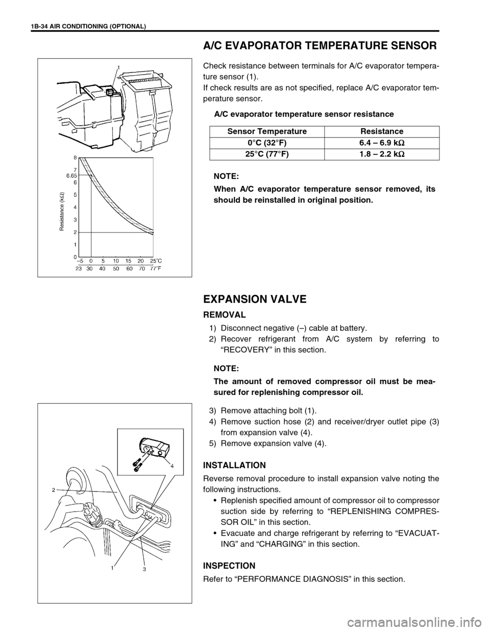
Check resistance between terminals for A/C evaporator tempera-
ture sensor (1).
If check results are as not specified, replace A/C evaporator tem-
perature sensor.
A/C evaporator temperature sensor resistance
EXPANSION VALVE
REMOVAL
1) Disconnect negative (–) cable at battery.
2) Recover refrigerant from A/C system by referring to
“RECOVERY” in this section.
3) Remove attaching bolt (1).
4) Remove suction hose (2) and receiver/dryer outlet pipe (3)
from expansion valve (4).
5) Remove expansion valve (4).
INSTALLATION
Reverse removal procedure to install expansion valve noting the
following instructions.
Replenish specified amount of compressor oil to compressor
suction side by referring to “REPLENISHING COMPRES-
SOR OIL” in this section.
Evacuate and charge refrigerant by referring to “EVACUAT-
ING” and “CHARGING” in this section.
INSPECTION
Refer to “PERFORMANCE DIAGNOSIS” in this section. Sensor Temperature Resistance
0°C (32°F) 6.4 – 6.9 k
Ω
ΩΩ Ω
25°C (77°F) 1.8 – 2.2 k
Ω
ΩΩ Ω
NOTE:
When A/C evaporator temperature sensor removed, its
should be reinstalled in original position.
NOTE:
The amount of removed compressor oil must be mea-
sured for replenishing compressor oil.
Page 352 of 698
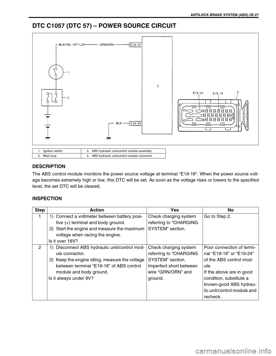
ANTILOCK BRAKE SYSTEM (ABS) 5E-27
DTC C1057 (DTC 57) – POWER SOURCE CIRCUIT
DESCRIPTION
The ABS control module monitors the power source voltage at terminal “E19-18”. When the power source volt-
age becomes extremely high or low, this DTC will be set. As soon as the voltage rises or lowers to the specified
level, the set DTC will be cleared.
INSPECTION
1. Ignition switch 3. ABS hydraulic unit/control module assembly
2. Main fuse 4. ABS hydraulic unit/control module connector
Step Action Yes No
1 1) Connect a voltmeter between battery posi-
tive (+) terminal and body ground.
2) Start the engine and measure the maximum
voltage when racing the engine.
Is it over 18V?Check charging system
referring to “CHARGING
SYSTEM” section.Go to Step 2.
2 1) Disconnect ABS hydraulic unit/control mod-
ule connector.
2) Keep the engine idling, measure the voltage
between terminal “E19-18” of ABS control
module and body ground.
Is it always under 9V?Check charging system
referring to “CHARGING
SYSTEM” section.
Imperfect short between
wire “GRN/ORN” and
ground.Poor connection of termi-
nal “E19-18” or “E19-24”
of the ABS control mod-
ule.
If the above are in good
condition, substitute a
known-good ABS hydrau-
lic unit/control module and
recheck.