2000 SUZUKI SWIFT ECM input
[x] Cancel search: ECM inputPage 460 of 698

ENGINE GENERAL INFORMATION AND DIAGNOSIS 6-91
DTC P0340 (DTC NO.15) CAMSHAFT POSITION (CMP) SENSOR CIRCUIT MAL-
FUNCTION
WIRING DIAGRAM / CIRCUIT DESCRIPTION
REFERENCE
Connect oscilloscope between terminals E21-11 of ECM connector connected to ECM and body ground and
check CMP sensor signal. When CKP circuit is failed (open or short), ECM identify the cylinder only by CMP
sensor signal.
DTC CONFIRMATION PROCEDURE
1) Clear DTC.
2) Start engine and keep it at idle for 1 min.
3) Select “DTC” mode on scan tool and check DTC.
ECM
5V+B
BLK/RED
RED/YEL
BLK/ORN
C42 (31P) C41 (24P) G02 (17P)1 2 3 4 5 6 7 8 9
10 11 12 13 14 15 16 17 18 19 20 21
22 23 24 25 26 28 27 29 30 315 6
1 2 3 4 5 6 7
11 12
9 10 11 13 12 14 15 16
16 171 2
7 8
13 14 3 4
9 10
15 17 188
19 20 21 22 23 24
C42-11
DTC DETECTING CONDITION POSSIBLE CAUSE
No CMP sensor signal during engine running (CKP
sensor signal is inputted).CMP sensor circuit open or short.
Signal rotor teeth damaged.
CMP sensor malfunction, foreign material being
attached or improper installation.
Incorrect starter signal.
ECM malfunction.
1. No.1 cylinder 3. No.3 cylinder [A] : Oscilloscope Waveforms [C] : CKP sensor signal
2. No.2 cylinder 4. No.4 cylinder [B] : Waveforms at specified idle speed [D] : CMP sensor signal
Page 472 of 698

ENGINE GENERAL INFORMATION AND DIAGNOSIS 6-103
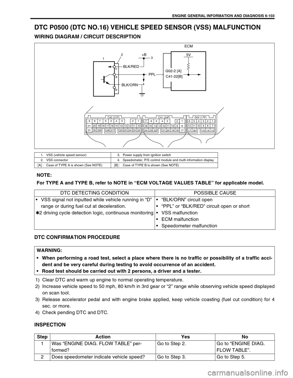
DTC P0500 (DTC NO.16) VEHICLE SPEED SENSOR (VSS) MALFUNCTION
WIRING DIAGRAM / CIRCUIT DESCRIPTION
DTC CONFIRMATION PROCEDURE
1) Clear DTC and warm up engine to normal operating temperature.
2) Increase vehicle speed to 50 mph, 80 km/h in 3rd gear or “2” range while observing vehicle speed displayed
on scan tool.
3) Release accelerator pedal and with engine brake applied, keep vehicle coasting (fuel cut condition) for 4
sec. or more.
4) Check pending DTC and DTC.
INSPECTION
1. VSS (vehicle speed sensor) 3. Power supply from ignition switch
2. VSS connector 4. Speedometer, P/S control module and multi information display
[A] : Case of TYPE A is shown (See NOTE) [B] : Case of TYPE B is shown (See NOTE)
ECM
5V+B
BLK/RED
BLK/ORN
PPL
C42 (31P) C41 (24P) G02 (17P)1 2 3 4 5 6 7 8 9
10 11 12 13 14 15 16 17 18 19 20 21
22 23 24 25 26 28 27 29 30 315 6
1 2 3 4 5 6 7
11 12
9 10 11 13 12 14 15 16
16 171 2
7 8
13 14 3 4
9 10
15 17 188
19 20 21 22 23 24
1
4 c
a
b2
3
G02-2 [A]
C41-22[B]
NOTE:
For TYPE A and TYPE B, refer to NOTE in “ECM VOLTAGE VALUES TABLE” for applicable model.
DTC DETECTING CONDITION POSSIBLE CAUSE
VSS signal not inputted while vehicle running in “D”
range or during fuel cut at deceleration.
✱2 driving cycle detection logic, continuous monitoring“BLK/ORN” circuit open
“PPL” or “BLK/RED” circuit open or short
VSS malfunction
ECM malfunction
Speedometer malfunction
WARNING:
When performing a road test, select a place where there is no traffic or possibility of a traffic acci-
dent and be very careful during testing to avoid occurrence of an accident.
Road test should be carried out with 2 persons, a driver and a tester.
Step Action Yes No
1Was “ENGINE DIAG. FLOW TABLE” per-
formed?Go to Step 2. Go to “ENGINE DIAG.
FLOW TABLE”.
2 Does speedometer indicate vehicle speed? Go to Step 3. Go to Step 5.
Page 477 of 698

6-108 ENGINE GENERAL INFORMATION AND DIAGNOSIS
DTC P1450 BAROMETRIC PRESSURE SENSOR LOW/HIGH INPUT
DTC P1451 BAROMETRIC PRESSURE SENSOR PERFORMANCE PROBLEM
WIRING DIAGRAM / CIRCUIT DESCRIPTION
Barometric pressure sensor is installed in ECM.
DTC CONFIRMATION PROCEDURE
1) Turn ignition switch OFF.
2) Clear DTC with ignition switch ON.
3) Turn ignition switch ON for 2 sec., crank engine for 2 sec. and run it at idle for 1 min.
4) Check pending DTC in “ON BOARD TEST” or “PENDING DTC” mode and DTC in “DTC” mode.
INSPECTION
DTC P1450 :
Substitute a known-good ECM and recheck.
DTC P1451 :
DTC DETECTING CONDITION POSSIBLE CAUSE
DTC P1450 :
Barometric pressure : Sensor voltage is 4.7 V or higher, or
1.6 V or lowerECM (barometric pressure sensor) malfunc-
tion
DTC P1451 :
Vehicle stopped
Engine cranking
Difference between barometric pressure and intake mani-
fold absolute pressure is 26 kPa, 200 mmHg or more
Difference between intake manifold absolute pressure at
engine start and the pressure after engine start is 1.3 kPa,
10 mmHg or less.
✱2 driving cycle detection logic, monitoring once/1 driving.Manifold absolute pressure sensor and its
circuit malfunction
ECM (barometric pressure sensor) malfunc-
tion
NOTE:
Note that atmospheric pressure varies depending on weather conditions as well as altitude.
Take that into consideration when performing these check.
Step Action Yes No
1 Check Barometric Pressure Valve.
1) Connect scan tool to DLC with ignition
switch OFF.
2) Turn ignition switch ON and select “DATA
LIST” mode on scan tool.
3) Check manifold absolute pressure. See Fig.
1.
Is it barometric pressure (approx. 100 kPa, 760
mmHg) at sea level?Substitute a known-good
ECM and recheck.Go to Step 2.
Page 481 of 698

6-112 ENGINE GENERAL INFORMATION AND DIAGNOSIS
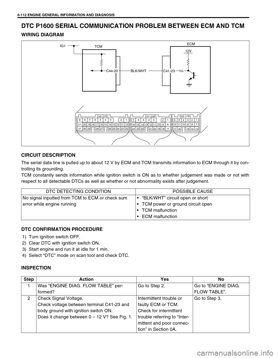
DTC P1600 SERIAL COMMUNICATION PROBLEM BETWEEN ECM AND TCM
WIRING DIAGRAM
CIRCUIT DESCRIPTION
The serial data line is pulled up to about 12 V by ECM and TCM transmits information to ECM through it by con-
trolling its grounding.
TCM constantly sends information while ignition switch is ON as to whether judgement was made or not with
respect to all detectable DTCs as well as whether or not abnormality exists after judgement.
DTC CONFIRMATION PROCEDURE
1) Turn ignition switch OFF.
2) Clear DTC with ignition switch ON.
3) Start engine and run it at idle for 1 min.
4) Select “DTC” mode on scan tool and check DTC.
INSPECTION
ECM
TCMIG1
BLK/WHT
12V
C42 (31P) C41 (24P) G02 (17P)1 2 3 4 5 6 7 8 9
10 11 12 13 14 15 16 17 18 19 20 21
22 23 24 25 26 28 27 29 30 315 6
1 2 3 4 5 6 7
11 12
9 10 11 13 12 14 15 16
16 171 2
7 8
13 14 3 4
9 10
15 17 188
19 20 21 22 23 24
C44-20
C41-23
DTC DETECTING CONDITION POSSIBLE CAUSE
No signal inputted from TCM to ECM or check sum
error while engine running“BLK/WHT” circuit open or short
TCM power or ground circuit open
TCM malfunction
ECM malfunction
Step Action Yes No
1Was “ENGINE DIAG. FLOW TABLE” per-
formed?Go to Step 2. Go to “ENGINE DIAG.
FLOW TABLE”.
2 Check Signal Voltage.
Check voltage between terminal C41-23 and
body ground with ignition switch ON.
Does it change between 0 – 12 V? See Fig. 1.Intermittent trouble or
faulty ECM or TCM.
Check for intermittent
trouble referring to “Inter-
mittent and poor connec-
tion” in Section 0A.Go to Step 3.
Page 483 of 698

6-114 ENGINE GENERAL INFORMATION AND DIAGNOSIS
DTC P1717 A/T DRIVE RANGE (PARK/NEUTRAL POSITION) SIGNAL CIRCUIT
MALFUNCTION
WIRING DIAGRAM / CIRCUIT DESCRIPTION
DTC CONFIRMATION PROCEDURE
1) Turn ignition switch OFF.
2) Clear DTC with ignition switch ON.
3) Start engine and shift selector lever to “D” range.
4) Increase vehicle speed to higher than 20 mph, 32 km/h and then stop vehicle.
5) Repeat above step 4) 9 times.
6) Shift selector lever to “2” range and repeat above step 4) and 5).
7) Shift selector lever to “L” range and repeat above step 4) and 5).
8) Check DTC in “DTC” mode and pending DTC in “ON BOARD TEST” or “PENDING DTC” mode.
1. From ignition switch 2. Transmission range switch
[A] : Case of TYPE A is shown (See NOTE) [B] : Case of TYPE B is shown (See NOTE)
TCMECMIG1
12V P
R
N
D
2
L
C42 (31P) C41 (24P) G02 (17P)1 2 3 4 5 6 7 8 9
10 11 12 13 14 15 16 17 18 19 20 21
22 23 24 25 26 28 27 29 30 315 6
1 2 3 4 5 6 7
11 12
9 10 11 13 12 14 15 16
16 171 2
7 8
13 14 3 4
9 10
15 17 188
19 20 21 22 23 24
IG11
C44-8
REDGRN/ORN1
2G02-6 [B] C41-14 [A]
C41-15 [A]
G02-2 [B] GRN RED [B]LT BLU [A]
NOTE:
For TYPE A and TYPE B, refer to NOTE in “ECM VOLTAGE VALUES TABLE” for applicable model.
DTC DETECTING CONDITION POSSIBLE CAUSE
“D” range signal not inputted (Park/Neutral position
signal inputted) to ECM while vehicle running
✱2 driving cycle detection logic, continuous monitor-
ing.“LT BLU” circuit open
Transmission range switch malfunction
“R”, “D”, “2” or “L” range signal circuit open
TCM power or ground circuit open
TCM malfunction
ECM malfunction
WARNING:
When performing a road test, select a place where there is no traffic or possibility of a traffic acci-
dent and be very careful during testing to avoid occurrence of an accident.
Road test should be carried out with 2 persons, a driver and a tester.
Page 492 of 698

ENGINE GENERAL INFORMATION AND DIAGNOSIS 6-123
Fig. 1 for Step 105 Check A/C (input) signal circuit referring to Step
1 of Table B-5 A/C Signal Circuit Check, if
equipped. (A/C signal can be also checked by
using SUZUKI scan tool.)
Is it in good condition?Go to Step 6. Repair or replace A/C sig-
nal circuit or A/C system.
6 Check IAC system referring to Step 2 of DTC
P0505 Diag. Flow Table.
Is check result satisfactory?Go to Step 7. Go to Step 3 of DTC
P0505 Diag. Flow Table.
7 Was IAC duty less than about 3% (or more than
about 97% for OFF duty meter) in Step 1 of this
table?Check abnormal air inhal-
ing from air intake system,
PCV valve and EVAP
canister purge control
system.Check TP sensor (closed
throttle position) and ECT
sensor for performance.
If sensors are OK, substi-
tute a known-good ECM.
8 Is SUZUKI scan Tool available? Go to Step 9. Go to Step 10.
9 Check PNP signal (“D” range signal).
1) Connect SUZUKI scan tool to DLC with igni-
tion switch OFF.
2) Turn ignition switch ON and check PNP sig-
nal (“P/N” and “D” range) on display when
shifting selector lever to each range. See
Table 1.
Is check result satisfactory?Go to Step 11. Repair or replace.
10 Check PNP signal (“D” range signal).
1) Turn ignition switch ON.
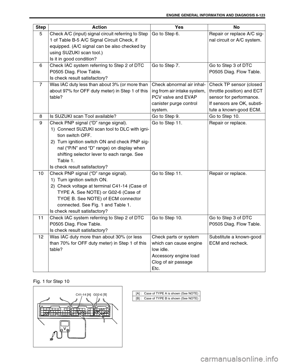
2) Check voltage at terminal C41-14 (Case of
TYPE A. See NOTE) or G02-6 (Case of
TYOE B. See NOTE) of ECM connector
connected. See Fig. 1 and Table 1.
Is check result satisfactory?Go to Step 11. Repair or replace.
11 Check IAC system referring to Step 2 of DTC
P0505 Diag. Flow Table.
Is check result satisfactory?Go to Step 10. Go to Step 3 of DTC
P0505 Diag. Flow Table.
12 Was IAC duty more than about 30% (or less
than 70% for OFF duty meter) in Step 1 of this
table?Check parts or system
which can cause engine
low idle.
Accessory engine load
Clog of air passage
Etc.Substitute a known-good
ECM and recheck. Step Action Yes No
[A] : Case of TYPE A is shown (See NOTE)
[B] : Case of TYPE B is shown (See NOTE)
Page 622 of 698

ENGINE AND EMISSION CONTROL SYSTEM 6E1-1
6F1
6F2
6G
6H
6E1
7A
7A1
7B1
7C1
7D
7E
7F
8A
8B
8C
8D
8E
9
10
10A
10B
SECTION 6E1
ENGINE AND EMISSION CONTROL SYSTEM
CONTENTS
GENERAL DESCRIPTION ............................ 6E1-2
AIR INTAKE SYSTEM ............................... 6E1-5
FUEL DELIVERY SYSTEM ....................... 6E1-6
FUEL PUMP ........................................... 6E1-6
ELECTRONIC CONTROL SYSTEM .......... 6E1-7
ENGINE & EMISSION CONTROL
INPUT/OUTPUT TABLE ........................ 6E1-8
ECM INPUT/OUTPUT CIRCUIT
DIAGRAM............................................... 6E1-9
ECM TERMINAL ARRANGEMENT
TABLE .................................................. 6E1-13
ON-VEHICLE SERVICE .............................. 6E1-15
ACCELERATOR CABLE
ADJUSTMENT ..................................... 6E1-15
IDLE SPEED/IDLE AIR CONTROL
(IAC) DUTY INSPECTION ................... 6E1-15
IDLE MIXTURE INSPECTION /
ADJUSTMENT (VEHICLE WITHOUT
HEATED OXYGEN SENSOR) ............. 6E1-17
AIR INTAKE SYSTEM ............................. 6E1-18
THROTTLE BODY ............................... 6E1-18IDLE AIR CONTROL VALVE (IAC
VALVE) ................................................ 6E1-20
FUEL DELIVERY SYSTEM ..................... 6E1-21
FUEL PRESSURE INSPECTION ........ 6E1-21
FUEL PUMP WITH PRESSURE
REGULATOR ....................................... 6E1-22
FUEL INJECTOR ................................. 6E1-23
ELECTRONIC CONTROL SYSTEM ....... 6E1-27
ENGINE CONTROL MODULE
(ECM) ................................................... 6E1-27
MANIFOLD ABSOLUTE PRESSURE
SENSOR (MAP SENSOR)................... 6E1-27
THROTTLE POSITION SENSOR (TP
SENSOR) ............................................. 6E1-28
INTAKE AIR TEMPERATURE
SENSOR (IAT SENSOR) ..................... 6E1-29
ENGINE COOLANT TEMPERATURE
SENSOR (ECT SENSOR) ................... 6E1-30
HEATED OXYGEN SENSOR (HO2S-1
AND HO2S-2) ...................................... 6E1-31
CAMSHAFT POSITION SENSOR ....... 6E1-32 WARNING:
For vehicles equipped with Supplemental Restraint (Air Bag) System :
Service on and around the air bag system components or wiring must be performed only by an
authorized SUZUKI dealer. Refer to “Air Bag System Components and Wiring Location View” under
“General Description” in air bag system section in order to confirm whether you are performing ser-
vice on or near the air bag system components or wiring. Please observe all WARNINGS and “Ser-
vice Precautions” under “On-Vehicle Service” in air bag system section before performing service
on or around the air bag system components or wiring. Failure to follow WARNINGS could result in
unintentional activation of the system or could render the system inoperative. Either of these two
conditions may result in severe injury.
Technical service work must be started at least 90 seconds after the ignition switch is turned to the
“LOCK” position and the negative cable is disconnected from the battery. Otherwise, the system
may be activated by reserve energy in the Sensing and Diagnostic Module (SDM).
NOTE:
Whether the following system (parts) are used in the particular vehicle or not depends on vehicle
specifications. Be sure to bear this in mind when performing service work.
EGR valve
Heated oxygen sensor(s) or CO adjusting resistor
Three way catalytic converter
Immobilizer indicator lamp
Knock sensor
Page 630 of 698

ENGINE AND EMISSION CONTROL SYSTEM 6E1-9
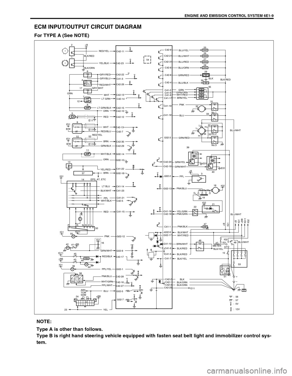
ECM INPUT/OUTPUT CIRCUIT DIAGRAM
For TYPE A (See NOTE)
37
C41-23
G02-12 IG1PNK 5554
BLK
C41-2
C41-9
C41-8
C41-17C42-13
17
2+B
1
6
8
5
IG1
IG1
14C42-9
C42-11
C42-23
C42-22
C41-3
C42-26
C42-14
C42-15
C42-10
C42-12
C42-13
C42-7
C42-30
C42-29
G02-14
G02-10
G02-16
C41-14
C41-21
C42-5
C41-15
G02-9
C42-17
G02-1
C42-28
C42-27 C42-16
G02-5C42-21
C42-31
C42-8
C42-6
C42-4
C41-19
C41-18
G02-3
G02-2
G02-13
C41-16
C42-18
C41-1
C41-10
C41-6
C41-5
C41-7
C42-1 C42-2
C42-3
C42-25G02-6
G02-173E01
E01 C42-20
C42-19L+
L–
H–H+ 25
26
27
28
29
30
35
31
No.1
No.2
No.3 32
33
33
33 34
IG2
IG2
+B
+B
IG1
+BB
IG11
IG2 IG1
21
47
49
IG
METERIG1
ST
15IG2
48
53
E11+
– 2218
PRND2L
IG11
IG11
+BB
IG145 41
ABS
TCM
SDM
24IG1
+BB50
16
E11
E1194
7
12
+BB
GND
: 56 : 57
IG1
E11 10
11
+B RED/YELBLU/YEL
BLU/WHT
BLU/RED
BLU/ORN
GRN/RED
BLU/BLK
PNK
BLU
GRN/RED
GRN/YEL39
40 GRN/WHT
PPL
YEL/GRN PNK/BLU
PNK/GRN
PNK/BLK
BLK/WHT
WHT/RED
BRN/WHT
BLK/RED
BLK/RED
BLK/YEL
BLK/ORNBLK
BLK/ORN YEL/BLK
GRY/RED
GRY/BLU
RED/WHT
GRY/WHT
LT GRN
LT GRN/BLK
ORN
RED
WHT
RED/BLU
BRN
GRN/BLK
WHT/BLK
ORN
BRN
EPS, AT, ETC
LT BLU
PPL
WHT/BLK
GRN/WHT
RED/BLK
PPL/YEL
PNK/BLU
WHT/GRN
BLU
B/W
B/W
BLK/WHT
RED
42
46 43
44 36
DN
TSGND MONPPL/WHT 38
G02-7
YEL
BLK/RED
GRN
GRN/ORN
BRN/YEL
51
2352
C41-22YEL/RED 13WHT
19
ORN
: 5V
: 12V
BLU/WHT
BLK/WHT
BLU/WHT
BLK/YEL
BLK/RED
BLK/ORN
WHT/RED
RED/YEL
NOTE:
Type A is other than follows.
Type B is right hand steering vehicle equipped with fasten seat belt light and immobilizer control sys-
tem.