2000 SUZUKI SWIFT check oil
[x] Cancel search: check oilPage 595 of 698
6B-6 ENGINE COOLING
MAINTENANCE
COOLANT LEVEL CHECK
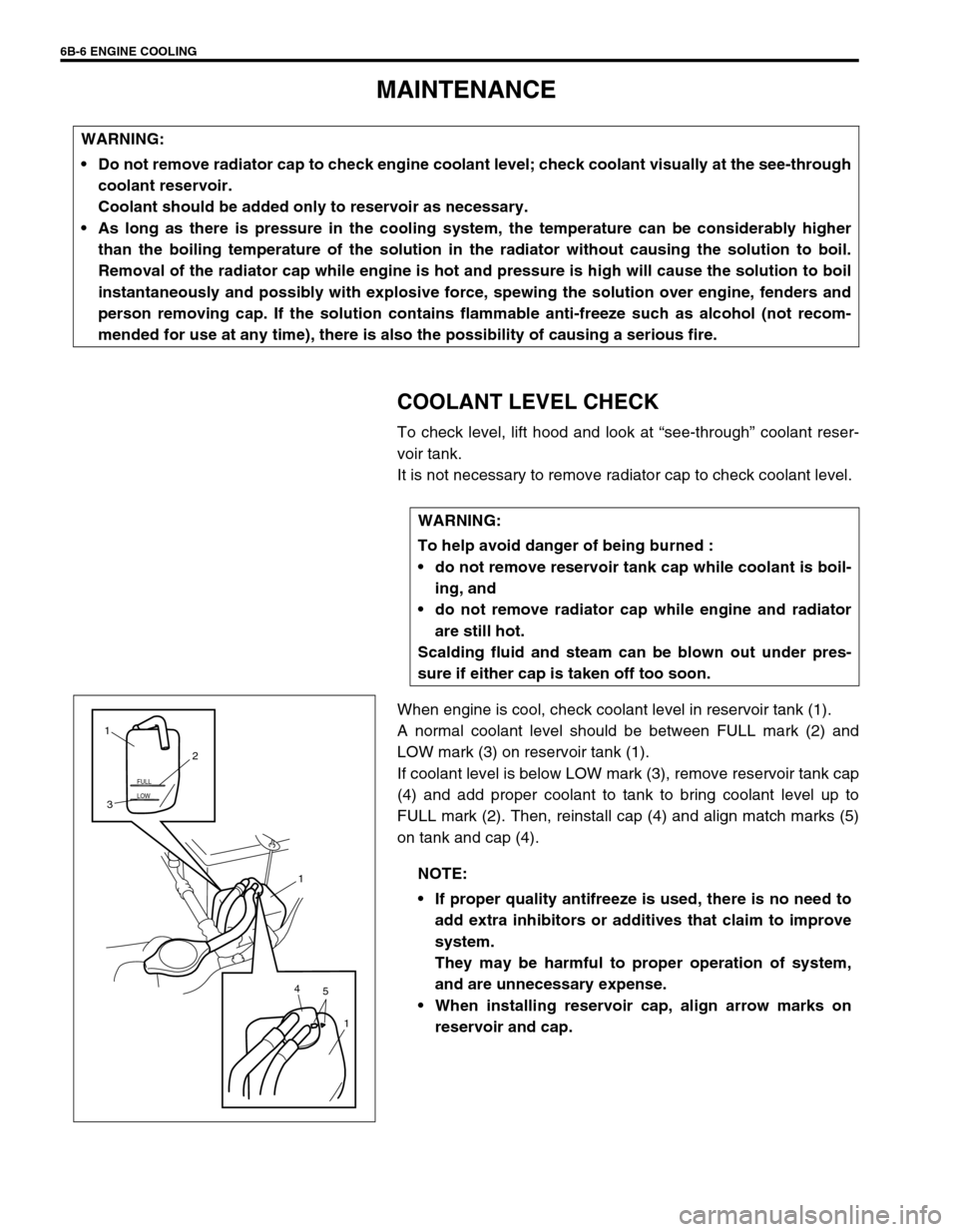
To check level, lift hood and look at “see-through” coolant reser-
voir tank.
It is not necessary to remove radiator cap to check coolant level.
When engine is cool, check coolant level in reservoir tank (1).
A normal coolant level should be between FULL mark (2) and
LOW mark (3) on reservoir tank (1).
If coolant level is below LOW mark (3), remove reservoir tank cap
(4) and add proper coolant to tank to bring coolant level up to
FULL mark (2). Then, reinstall cap (4) and align match marks (5)
on tank and cap (4). WARNING:
Do not remove radiator cap to check engine coolant level; check coolant visually at the see-through
coolant reservoir.
Coolant should be added only to reservoir as necessary.
As long as there is pressure in the cooling system, the temperature can be considerably higher
than the boiling temperature of the solution in the radiator without causing the solution to boil.
Removal of the radiator cap while engine is hot and pressure is high will cause the solution to boil
instantaneously and possibly with explosive force, spewing the solution over engine, fenders and
person removing cap. If the solution contains flammable anti-freeze such as alcohol (not recom-
mended for use at any time), there is also the possibility of causing a serious fire.
WARNING:
To help avoid danger of being burned :
do not remove reservoir tank cap while coolant is boil-
ing, and
do not remove radiator cap while engine and radiator
are still hot.
Scalding fluid and steam can be blown out under pres-
sure if either cap is taken off too soon.
NOTE:
If proper quality antifreeze is used, there is no need to
add extra inhibitors or additives that claim to improve
system.
They may be harmful to proper operation of system,
and are unnecessary expense.
When installing reservoir cap, align arrow marks on
reservoir and cap.
LOW FULL
5 41
1 32 1
Page 619 of 698

6C-12 ENGINE FUEL
DISASSEMBLY AND REASSEMBLY
Disassemble and reassemble fuel pump assembly, noting the fol-
lowings.
When removing fuel level sensor (3), press snap-fit part (4)
and slide it in the arrow direction as shown in figure.
When installing fuel level sensor to housing, fit fuel level sen-
sor securely.
“A” : Apply oil 5. O-ring 10. Fuel pressure regulator
1. Fuel filter assembly (including check valve) 6. Fuel level sensor (Fuel sender gauge) 11. Gasket
2. Grommet 7. Fuel pump 12. Fuel pump plate
3. Tube 8. Cushion Do not reuse.
4. Housing 9. Bracket
CAUTION:
While removing fuel level gauge, do not contact resis-
tor plate (1) or deform arm (2). It may cause fuel level
gauge to fail.
When removing grommet from fuel tube or bracket sub
assembly, be very careful not to cause damage to
grommet installed section (sealed section in bore).
Should it be damaged, replace it with new one, or fuel
will leak from that part.
Page 665 of 698
IGNITION SYSTEM (ELECTRONIC IGNITION SYSTEM 6F1-3
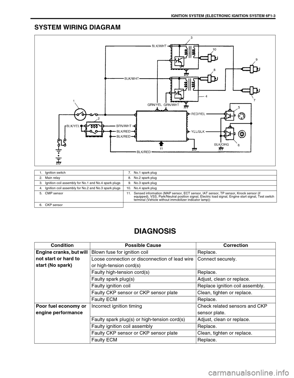
SYSTEM WIRING DIAGRAM
DIAGNOSIS
1. Ignition switch 7. No.1 spark plug
2. Main relay 8. No.2 spark plug
3. Ignition coil assembly for No.1 and No.4 spark plugs 9. No.3 spark plug
4. Ignition coil assembly for No.2 and No.3 spark plugs 10. No.4 spark plug
5. CMP sensor 11. Sensed information (MAP sensor, ECT sensor, IAT sensor, TP sensor, Knock sensor (if
equipped), VSS, Park/Neutral position signal, Electric load signal, Engine start signal, Test switch
terminal (Vehicle without immobilizer indicator lamp))
6. CKP sensor
Condition Possible Cause Correction
Engine cranks, but will
not start or hard to
start (No spark)Blown fuse for ignition coil Replace.
Loose connection or disconnection of lead wire
or high-tension cord(s)Connect securely.
Faulty high-tension cord(s) Replace.
Faulty spark plug(s) Adjust, clean or replace.
Faulty ignition coil Replace ignition coil assembly.
Faulty CKP sensor or CKP sensor plate Clean, tighten or replace.
Faulty ECM Replace.
Poor fuel economy or
engine performanceIncorrect ignition timing Check related sensors and CKP
sensor plate.
Faulty spark plug(s) or high-tension cord(s) Adjust, clean or replace.
Faulty ignition coil assembly Replace.
Faulty CKP sensor or CKP sensor plate Clean, tighten or replace.
Faulty ECM Replace.
Page 666 of 698
6F1-4 IGNITION SYSTEM (ELECTRONIC IGNITION SYSTEM)
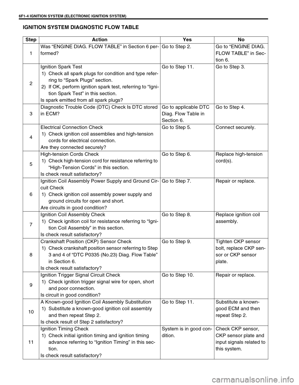
IGNITION SYSTEM DIAGNOSTIC FLOW TABLE
Step Action Yes No
1Was “ENGINE DIAG. FLOW TABLE” in Section 6 per-
formed?Go to Step 2. Go to “ENGINE DIAG.
FLOW TABLE” in Sec-
tion 6.
2Ignition Spark Test
1) Check all spark plugs for condition and type refer-
ring to “Spark Plugs” section.
2) If OK, perform ignition spark test, referring to “Igni-
tion Spark Test” in this section.
Is spark emitted from all spark plugs?Go to Step 11. Go to Step 3.
3Diagnostic Trouble Code (DTC) Check Is DTC stored
in ECM?Go to applicable DTC
Diag. Flow Table in
Section 6.Go to Step 4.
4Electrical Connection Check
1) Check ignition coil assemblies and high-tension
cords for electrical connection.
Are they connected securely?Go to Step 5. Connect securely.
5High-tension Cords Check
1) Check high-tension cord for resistance referring to
“High-Tension Cords” in this section.
Is check result satisfactory?Go to Step 6. Replace high-tension
cord(s).
6Ignition Coil Assembly Power Supply and Ground Cir-
cuit Check
1) Check ignition coil assembly power supply and
ground circuits for open and short.
Are circuits in good condition?Go to Step 7. Repair or replace.
7Ignition Coil Assembly Check
1) Check ignition coil for resistance referring to “Igni-
tion Coil Assembly” in this section.
Is check result satisfactory?Go to Step 8. Replace ignition coil
assembly.
8Crankshaft Position (CKP) Sensor Check
1) Check crankshaft position sensor referring to Step
3 and 4 of “DTC P0335 (No.23) Diag. Flow Table”
in Section 6.
Is check result satisfactory?Go to Step 9. Tighten CKP sensor
bolt, replace CKP sen-
sor or CKP sensor
plate.
9Ignition Trigger Signal Circuit Check
1) Check ignition trigger signal wire for open, short
and poor connection.
Is circuit in good condition?Go to Step 10. Repair or replace.
10A Known-good Ignition Coil Assembly Substitution
1) Substitute a known-good ignition coil assembly
and then repeat Step 2.
Is check result of Step 2 satisfactory?Go to Step 11. Substitute a known-
good ECM and then
repeat Step 2.
11Ignition Timing Check
1) Check initial ignition timing and ignition timing
advance referring to “Ignition Timing” in this sec-
tion.
Is check result satisfactory?System is in good con-
dition.Check CKP sensor,
CKP sensor plate and
input signals related to
this system.
Page 667 of 698
IGNITION SYSTEM (ELECTRONIC IGNITION SYSTEM 6F1-5
ON-VEHICLE SERVICE
IGNITION SPARK TEST
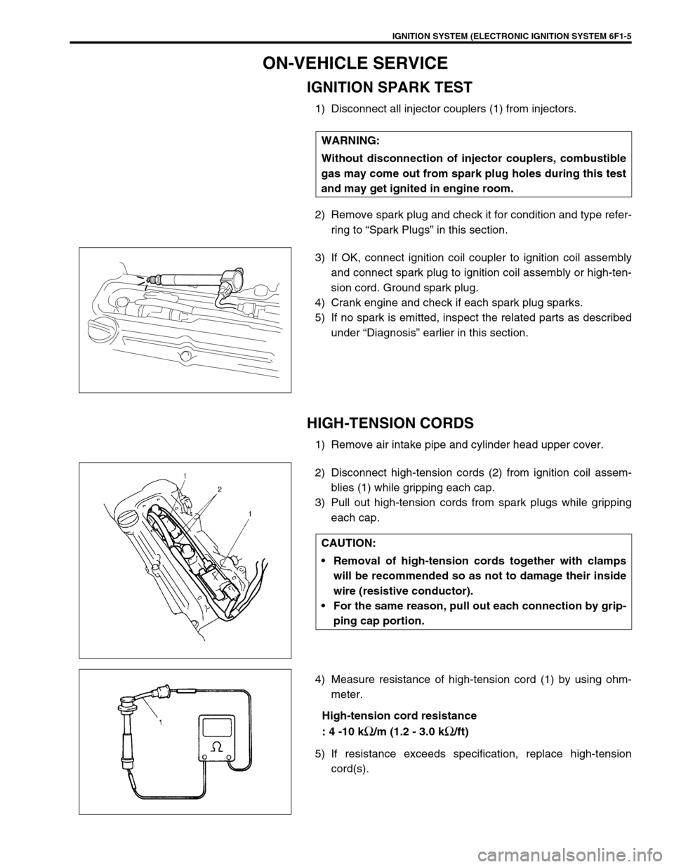
1) Disconnect all injector couplers (1) from injectors.
2) Remove spark plug and check it for condition and type refer-
ring to “Spark Plugs” in this section.
3) If OK, connect ignition coil coupler to ignition coil assembly
and connect spark plug to ignition coil assembly or high-ten-
sion cord. Ground spark plug.
4) Crank engine and check if each spark plug sparks.
5) If no spark is emitted, inspect the related parts as described
under “Diagnosis” earlier in this section.
HIGH-TENSION CORDS
1) Remove air intake pipe and cylinder head upper cover.
2) Disconnect high-tension cords (2) from ignition coil assem-
blies (1) while gripping each cap.
3) Pull out high-tension cords from spark plugs while gripping
each cap.
4) Measure resistance of high-tension cord (1) by using ohm-
meter.
High-tension cord resistance
: 4 -10 k
Ω/m (1.2 - 3.0 kΩ/ft)
5) If resistance exceeds specification, replace high-tension
cord(s). WARNING:
Without disconnection of injector couplers, combustible
gas may come out from spark plug holes during this test
and may get ignited in engine room.
CAUTION:
Removal of high-tension cords together with clamps
will be recommended so as not to damage their inside
wire (resistive conductor).
For the same reason, pull out each connection by grip-
ping cap portion.
Page 674 of 698
6G-2 CRANKING SYSTEM
GENERAL DESCRIPTION
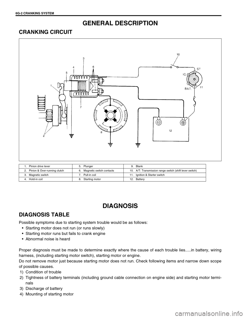
CRANKING CIRCUIT
DIAGNOSIS
DIAGNOSIS TABLE
Possible symptoms due to starting system trouble would be as follows:
Starting motor does not run (or runs slowly)
Starting motor runs but fails to crank engine
Abnormal noise is heard
Proper diagnosis must be made to determine exactly where the cause of each trouble lies.....in battery, wiring
harness, (including starting motor switch), starting motor or engine.
Do not remove motor just because starting motor does not run. Check following items and narrow down scope
of possible causes.
1) Condition of trouble
2) Tightness of battery terminals (including ground cable connection on engine side) and starting motor termi-
nals
3) Discharge of battery
4) Mounting of starting motor
1. Pinion drive lever 5. Plunger 9. Blank
2. Pinion & Over-running clutch 6. Magnetic switch contacts 10. A/T: Transmission range switch (shift lever switch)
3. Magnetic switch 7. Pull-in coil 11. Ignition & Starter switch
4. Hold-in coil 8. Starting motor 12. Battery
Page 676 of 698

6G-4 CRANKING SYSTEM
PERFORMANCE TEST
PULL-IN TEST
Connect battery to magnetic switch as shown.
Check that plunger and pinion move outward.
If plunger and pinion don’t move, replace magnetic switch.
HOLD-IN TEST
While connected as above with plunger out, disconnect negative
lead from terminal “M”.
Check that plunger and pinion remain out.
If plunger and pinion return inward, replace magnetic switch.
PLUNGER AND PINION RETURN TEST
Disconnect negative lead from starting motor body.
Check that plunger and pinion return inward.
If plunger and pinion don’t return, replace magnetic switch. CAUTION:
Each test must be performed within 3 - 5 seconds to
avoid coil from burning.
NOTE:
Before testing, disconnect lead wire from terminal M.
1. Terminal “S”
2. Terminal “M”
3. Lead wire (switch to motor)
Page 686 of 698
6H-6 CHARGING SYSTEM
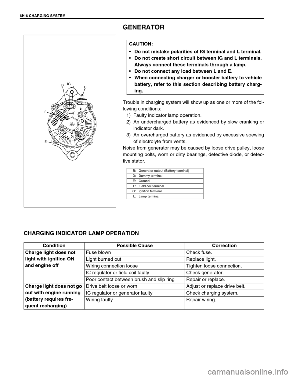
GENERATOR
Trouble in charging system will show up as one or more of the fol-
lowing conditions:
1) Faulty indicator lamp operation.
2) An undercharged battery as evidenced by slow cranking or
indicator dark.
3) An overcharged battery as evidenced by excessive spewing
of electrolyte from vents.
Noise from generator may be caused by loose drive pulley, loose
mounting bolts, worn or dirty bearings, defective diode, or defec-
tive stator.
CHARGING INDICATOR LAMP OPERATION
CAUTION:
Do not mistake polarities of IG terminal and L terminal.
Do not create short circuit between IG and L terminals.
Always connect these terminals through a lamp.
Do not connect any load between L and E.
When connecting charger or booster battery to vehicle
battery, refer to this section describing battery charg-
ing.
B: Generator output (Battery terminal)
D: Dummy terminal
E: Ground
F: Field coil terminal
IG: Ignition terminal
L: Lamp terminal
Condition Possible Cause Correction
Charge light does not
light with ignition ON
and engine offFuse blown Check fuse.
Light burned out Replace light.
Wiring connection loose Tighten loose connection.
IC regulator or field coil faulty Check generator.
Poor contact between brush and slip ring Repair or replace.
Charge light does not go
out with engine running
(battery requires fre-
quent recharging)Drive belt loose or worn Adjust or replace drive belt.
IC regulator or generator faulty Check charging system.
Wiring faulty Repair wiring.