Page 365 of 698
5E-40 ANTILOCK BRAKE SYSTEM (ABS)
SENSOR ROTOR INSPECTION
Check rotor serration (teeth) for being missing, damaged or
deformed.
Turn wheel and check if rotor rotation is free from eccentric-
ity and looseness.
Check that no foreign material is attached.
If any faulty is found, repair or replace.
INSTALLATION
Reverse removal procedure for installation noting the following.
Check that no foreign material is attached to sensor (1) and
ring.
Be sure to install wheel speed sensor and its bolt at the cor-
rect (upper) position as shown in figure.
Tighten sensor bolt to specified torque.
Tightening torque
Sensor bolt (a) : 10 N·m (1.0 kg-m, 7.5 lb-ft)
Check that there is no clearance between sensor and rear
axle shaft.
[A] : For 2WD
[B] : For 4WD
[B] [A]
1
CAUTION:
Do not pull or twist wire harness more than necessary
when installing rear wheel speed sensor.
Page 366 of 698
ANTILOCK BRAKE SYSTEM (ABS) 5E-41
REAR WHEEL SPEED SENSOR RING (FOR
2WD VEHICLE)
REMOVAL
1) Remove rear wheel sensor from rear axle housing.
2) Remove brake drum referring to Section 5.
3) Remove sensor ring (1) from brake drum (2) using special
tools.
Special tool
(A) : 09913-75520
(B) : 09913-65135
INSTALLATION
1) Install new sensor ring (1) to brake drum (2) using special
tool and hydraulic press (3).
Special tool
(A) : 09913-75840
2) Install brake drum. Refer to Section 5.
3) Install rear wheel speed sensor (1) to rear axle housing.
Tightening torque
Rear wheel speed sensor (a) : 10 N·m (1.0 kg-m, 7.5 lb-ft) CAUTION:
Pull out sensor ring from brake drum gradually and
evenly. Attempt to pull it out partially may cause it to be
deformed.
NOTE:
Do not reuse (reinstall) removed sensor ring.
1
(a)
Page 367 of 698
5E-42 ANTILOCK BRAKE SYSTEM (ABS)
REAR WHEEL SPEED SENSOR RING (FOR
4WD VEHICLE)
REMOVAL
1) Remove rear axle shaft referring to Section 3E.
2) Remove rear wheel sensor ring from axle shaft by using spe-
cial tools.
Special tool
(A) : 09927-18411
(B) : 09921-57810
INSTALLATION
1) Install new wheel sensor ring (1) by using hydraulic press
(2).
2) Install rear axle shaft referring to Section 3E.
3) Install wheel speed sensor to rear axle housing.
Tightening torque
Wheel sensor ring bolt : 10 N·m (1.0 kg-m, 7.5 lb-ft)
NOTE:
Do not reuse (reinstall) removed sensor ring.
Do not damage to retainer ring when press fitting
wheel sensor ring.
1 2
Page 368 of 698

ANTILOCK BRAKE SYSTEM (ABS) 5E-43
G SENSOR (FOR 4WD VEHICLE ONLY)
REMOVAL
1) Turn ignition switch OFF and disconnect battery negative
cable.
2) Remove ABS fuse from fuse box.
3) Disconnect ABS hydraulic unit/control module assembly
connector by pulling up lock.
4) Remove center console box.
5) Remove G sensor (1) from floor.
6) Disconnect connector from sensor.
INSPECTION
Connect positive cable of 12 volt battery to “A” terminal of sensor
and ground cable to “C” terminal. Then using voltmeter, check
voltage between “B” terminal and “C” terminal.
G sensor specification
When placed horizontally : 2 – 3 V
When placed upright with arrow upward : 3 – 4 V
When placed upright with arrow downward : 1 – 2 V
If measured voltage is not as specified, replace sensor.
INSTALLATION
1) Connect connector to sensor securely.
2) Install sensor onto floor so that arrow mark directs vehicle
forward.
3) Connect ABS hydraulic unit/control module assembly con-
nector.
4) Install ABS fuse to fuse box.
5) Install rear console box.CAUTION:
Sensor must not be dropped or shocked. It will affect its
original performance.
2. Label1
2
[A] : Horizontal
[B] : Upright with arrow upward
[C] : Upright with arrow downward
Page 369 of 698
5E-44 ANTILOCK BRAKE SYSTEM (ABS)
SPECIAL TOOL
09913-65135 09913-75520 09913-75840 09927-18411
Bearing puller Bearing installing tool Sensor ring installer Universal puller
09921-57810 09931-76011 09931-76030
Countershaft holder Tech 1A kit
(See NOTE below.)Mass storage cartridge 16/14 pin DLC cable
09950-78220
Flare nut wrench (10 mm)
NOTE:
This kit includes the following items.
1. Storage case, 2. Operator's manual, 3. Tech 1A, 4. DLC cable, 5. Test lead/probe,
6. Power source cable, 7. DLC cable adaptor, 8. Self-test adaptor
Page 375 of 698

6-6 ENGINE GENERAL INFORMATION AND DIAGNOSIS
FUEL PRESSURE RELIEF PROCEDURE
After making sure that engine is cold, release fuel pressure as fol-
lows.
1) Place transmission gear shift lever in “Neutral” (Shift selector
lever to “P” range for A/T model), set parking brake, and
block drive wheels.
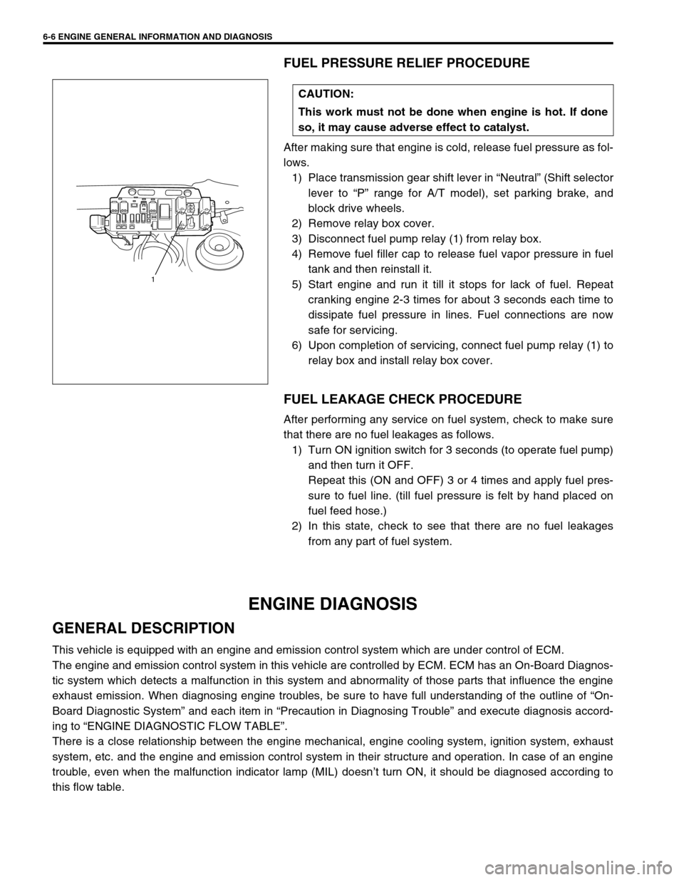
2) Remove relay box cover.
3) Disconnect fuel pump relay (1) from relay box.
4) Remove fuel filler cap to release fuel vapor pressure in fuel
tank and then reinstall it.
5) Start engine and run it till it stops for lack of fuel. Repeat
cranking engine 2-3 times for about 3 seconds each time to
dissipate fuel pressure in lines. Fuel connections are now
safe for servicing.
6) Upon completion of servicing, connect fuel pump relay (1) to
relay box and install relay box cover.
FUEL LEAKAGE CHECK PROCEDURE
After performing any service on fuel system, check to make sure
that there are no fuel leakages as follows.
1) Turn ON ignition switch for 3 seconds (to operate fuel pump)
and then turn it OFF.
Repeat this (ON and OFF) 3 or 4 times and apply fuel pres-
sure to fuel line. (till fuel pressure is felt by hand placed on
fuel feed hose.)
2) In this state, check to see that there are no fuel leakages
from any part of fuel system.
ENGINE DIAGNOSIS
GENERAL DESCRIPTION
This vehicle is equipped with an engine and emission control system which are under control of ECM.
The engine and emission control system in this vehicle are controlled by ECM. ECM has an On-Board Diagnos-
tic system which detects a malfunction in this system and abnormality of those parts that influence the engine
exhaust emission. When diagnosing engine troubles, be sure to have full understanding of the outline of “On-
Board Diagnostic System” and each item in “Precaution in Diagnosing Trouble” and execute diagnosis accord-
ing to “ENGINE DIAGNOSTIC FLOW TABLE”.
There is a close relationship between the engine mechanical, engine cooling system, ignition system, exhaust
system, etc. and the engine and emission control system in their structure and operation. In case of an engine
trouble, even when the malfunction indicator lamp (MIL) doesn’t turn ON, it should be diagnosed according to
this flow table.CAUTION:
This work must not be done when engine is hot. If done
so, it may cause adverse effect to catalyst.
1
Page 396 of 698

ENGINE GENERAL INFORMATION AND DIAGNOSIS 6-27
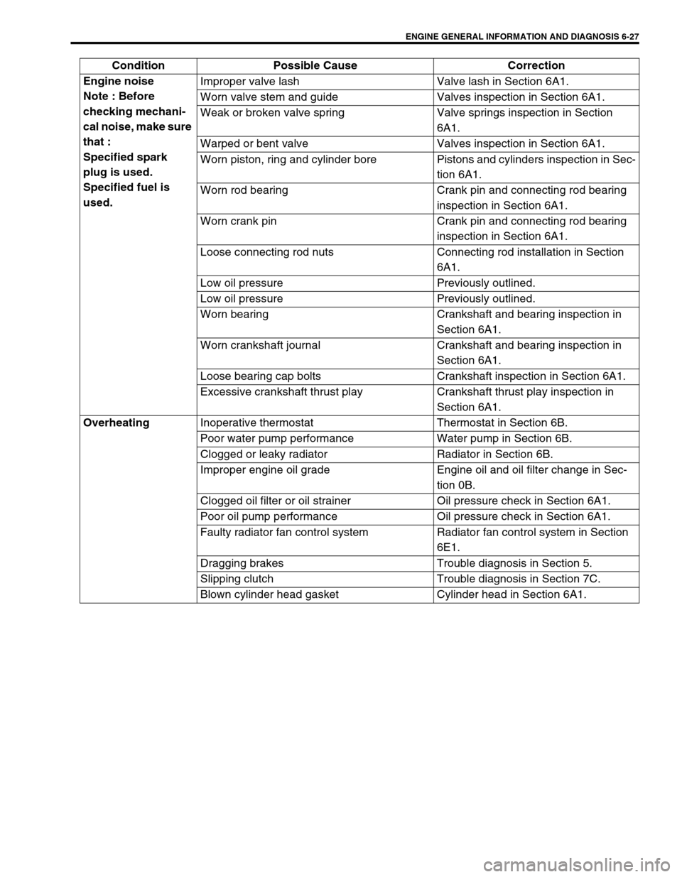
Engine noise
Note : Before
checking mechani-
cal noise, make sure
that :
Specified spark
plug is used.
Specified fuel is
used.Improper valve lash Valve lash in Section 6A1.
Worn valve stem and guide Valves inspection in Section 6A1.
Weak or broken valve spring Valve springs inspection in Section
6A1.
Warped or bent valve Valves inspection in Section 6A1.
Worn piston, ring and cylinder bore Pistons and cylinders inspection in Sec-
tion 6A1.
Worn rod bearing Crank pin and connecting rod bearing
inspection in Section 6A1.
Worn crank pin Crank pin and connecting rod bearing
inspection in Section 6A1.
Loose connecting rod nuts Connecting rod installation in Section
6A1.
Low oil pressure Previously outlined.
Low oil pressure Previously outlined.
Worn bearing Crankshaft and bearing inspection in
Section 6A1.
Worn crankshaft journal Crankshaft and bearing inspection in
Section 6A1.
Loose bearing cap bolts Crankshaft inspection in Section 6A1.
Excessive crankshaft thrust play Crankshaft thrust play inspection in
Section 6A1.
Overheating
Inoperative thermostat Thermostat in Section 6B.
Poor water pump performance Water pump in Section 6B.
Clogged or leaky radiator Radiator in Section 6B.
Improper engine oil grade Engine oil and oil filter change in Sec-
tion 0B.
Clogged oil filter or oil strainer Oil pressure check in Section 6A1.
Poor oil pump performance Oil pressure check in Section 6A1.
Faulty radiator fan control system Radiator fan control system in Section
6E1.
Dragging brakes Trouble diagnosis in Section 5.
Slipping clutch Trouble diagnosis in Section 7C.
Blown cylinder head gasket Cylinder head in Section 6A1. Condition Possible Cause Correction
Page 397 of 698

6-28 ENGINE GENERAL INFORMATION AND DIAGNOSIS
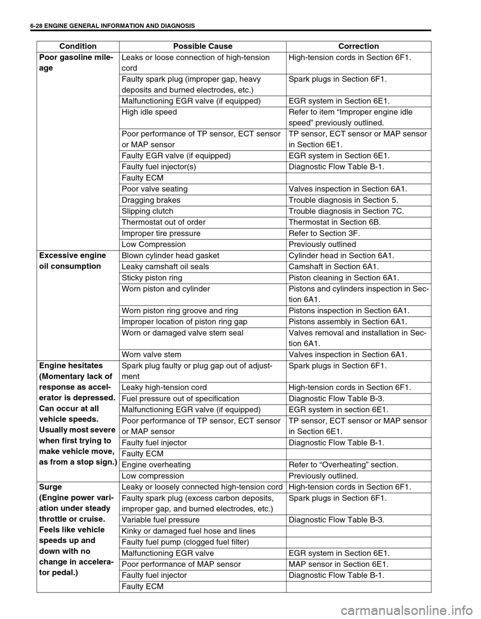
Poor gasoline mile-
age Leaks or loose connection of high-tension
cordHigh-tension cords in Section 6F1.
Faulty spark plug (improper gap, heavy
deposits and burned electrodes, etc.)Spark plugs in Section 6F1.
Malfunctioning EGR valve (if equipped) EGR system in Section 6E1.
High idle speed Refer to item “Improper engine idle
speed” previously outlined.
Poor performance of TP sensor, ECT sensor
or MAP sensorTP sensor, ECT sensor or MAP sensor
in Section 6E1.
Faulty EGR valve (if equipped) EGR system in Section 6E1.
Faulty fuel injector(s) Diagnostic Flow Table B-1.
Faulty ECM
Poor valve seating Valves inspection in Section 6A1.
Dragging brakes Trouble diagnosis in Section 5.
Slipping clutch Trouble diagnosis in Section 7C.
Thermostat out of order Thermostat in Section 6B.
Improper tire pressure Refer to Section 3F.
Low Compression Previously outlined
Excessive engine
oil consumption Blown cylinder head gasket Cylinder head in Section 6A1.
Leaky camshaft oil seals Camshaft in Section 6A1.
Sticky piston ring Piston cleaning in Section 6A1.
Worn piston and cylinder Pistons and cylinders inspection in Sec-
tion 6A1.
Worn piston ring groove and ring Pistons inspection in Section 6A1.
Improper location of piston ring gap Pistons assembly in Section 6A1.
Worn or damaged valve stem seal Valves removal and installation in Sec-
tion 6A1.
Worn valve stem Valves inspection in Section 6A1.
Engine hesitates
(Momentary lack of
response as accel-
erator is depressed.
Can occur at all
vehicle speeds.
Usually most severe
when first trying to
make vehicle move,
as from a stop sign.)Spark plug faulty or plug gap out of adjust-
mentSpark plugs in Section 6F1.
Leaky high-tension cord High-tension cords in Section 6F1.
Fuel pressure out of specification Diagnostic Flow Table B-3.
Malfunctioning EGR valve (if equipped) EGR system in section 6E1.
Poor performance of TP sensor, ECT sensor
or MAP sensorTP sensor, ECT sensor or MAP sensor
in Section 6E1.
Faulty fuel injector Diagnostic Flow Table B-1.
Faulty ECM
Engine overheating Refer to “Overheating” section.
Low compression Previously outlined.
Surge
(Engine power vari-
ation under steady
throttle or cruise.
Feels like vehicle
speeds up and
down with no
change in accelera-
tor pedal.)Leaky or loosely connected high-tension cord High-tension cords in Section 6F1.
Faulty spark plug (excess carbon deposits,
improper gap, and burned electrodes, etc.)Spark plugs in Section 6F1.
Variable fuel pressure Diagnostic Flow Table B-3.
Kinky or damaged fuel hose and lines
Faulty fuel pump (clogged fuel filter)
Malfunctioning EGR valve EGR system in Section 6E1.
Poor performance of MAP sensor MAP sensor in Section 6E1.
Faulty fuel injector Diagnostic Flow Table B-1.
Faulty ECM Condition Possible Cause Correction