Page 50 of 698

MAINTENANCE AND LUBRICATION 0B-21
STEERING
Check to ensure that steering wheel is free from instability, or abnormally heavy feeling.
Check that the vehicle does not wander or pull to one side.
ENGINE
Check that engine responds readily at all speeds.
Check that engine is free from abnormal noise and abnormal vibration.
BODY, WHEELS AND POWER TRANSMITTING SYSTEM
Check that body, wheels and power transmitting system are free from abnormal noise and abnormal vibration or
any other abnormal condition.
METERS AND GAUGE
Check that speedometer, odometer, fuel meter, temperature gauge, etc. are operating accurately.
LIGHTS
Check that all lights operate properly.
WINDSHIELD DEFROSTER
Periodically check that air comes out from defroster outlet when operating heater or air conditioning.
Set mode control lever to defroster position and fan switch lever to “HI” position for this check.
RECOMMENDED FLUIDS AND LUBRICANTS
Engine oil SE, SF, SG, SH or SJ grade (Refer to “ENGINE OIL AND OIL FILTER”
in this section for engine oil viscosity.)
Engine coolant
(Ethylene glycol base coolant)“Antifreeze/Anticorrosion coolant”
Brake fluid DOT 3
Manual transmission oil Refer to “M/T OIL CHANGE” in Section 7A.
Transfer oil (4WD) Refer to “TRANSFER OIL CHANGE” in Section 7D.
Differential oil (4WD) Refer to “DIFFERENTIAL OIL CHANGE” in Section 7F.
Automatic transmission fluid
An equivalent of DEXRON
®-III
Door hinges Engine oil or water resistance chassis grease
Hood latch assembly Engine oil or water resistance chassis grease
Key lock cylinder Spray lubricant
Page 128 of 698

MANUAL RACK AND PINION 3B-7
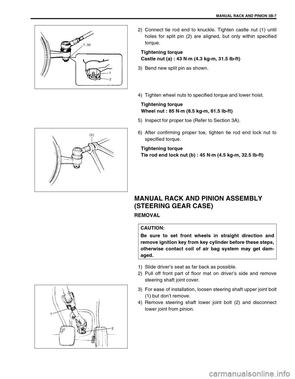
2) Connect tie rod end to knuckle. Tighten castle nut (1) until
holes for split pin (2) are aligned, but only within specified
torque.
Tightening torque
Castle nut (a) : 43 N·m (4.3 kg-m, 31.5 lb-ft)
3) Bend new split pin as shown.
4) Tighten wheel nuts to specified torque and lower hoist.
Tightening torque
Wheel nut : 85 N·m (8.5 kg-m, 61.5 lb-ft)
5) Inspect for proper toe (Refer to Section 3A).
6) After confirming proper toe, tighten tie rod end lock nut to
specified torque.
Tightening torque
Tie rod end lock nut (b) : 45 N·m (4.5 kg-m, 32.5 lb-ft)
MANUAL RACK AND PINION ASSEMBLY
(STEERING GEAR CASE)
REMOVAL
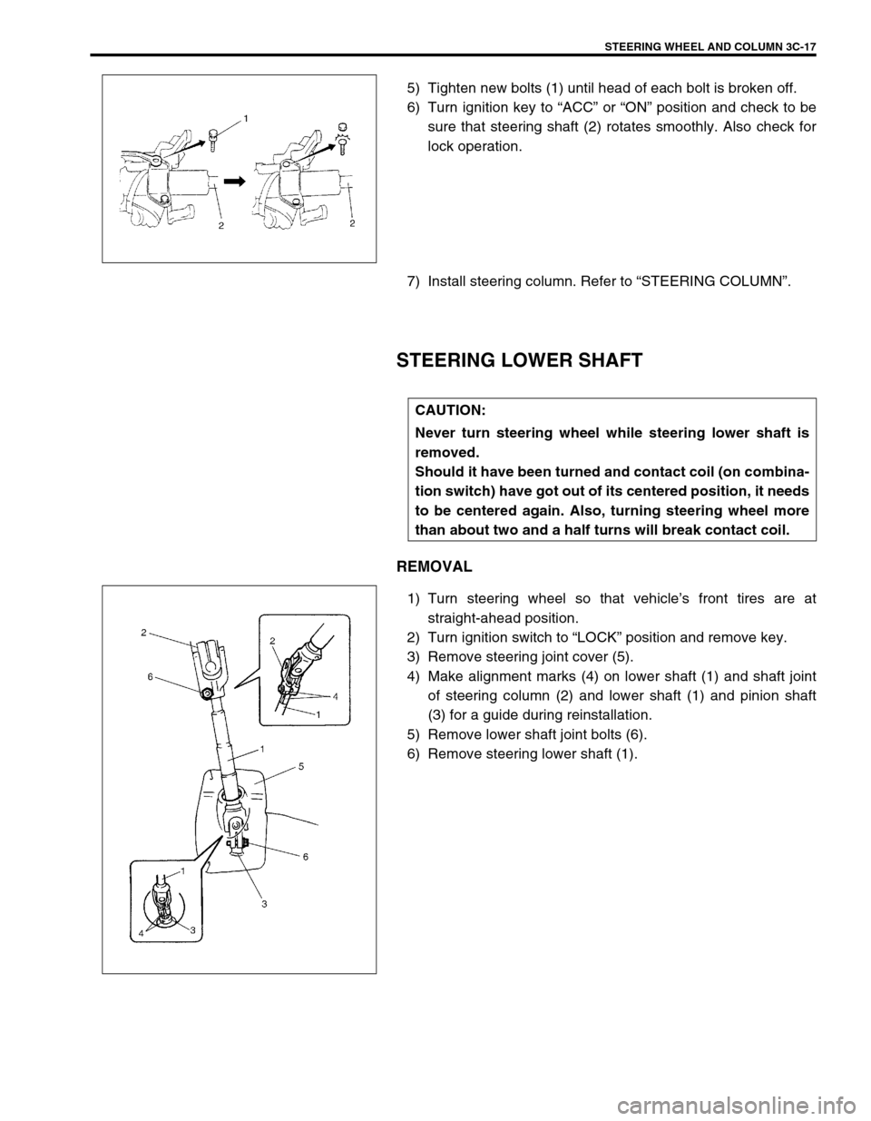
1) Slide driver’s seat as far back as possible.
2) Pull off front part of floor mat on driver’s side and remove
steering shaft joint cover.
3) For ease of installation, loosen steering shaft upper joint bolt
(1) but don’t remove.
4) Remove steering shaft lower joint bolt (2) and disconnect
lower joint from pinion.
CAUTION:
Be sure to set front wheels in straight direction and
remove ignition key from key cylinder before these steps,
otherwise contact coil of air bag system may get dam-
aged.
Page 184 of 698
STEERING WHEEL AND COLUMN 3C-11
REMOVAL
1) Disconnect negative cable at battery.
2) Disable air bag system. Refer to “DISABLING AIR BAG
SYSTEM” under “SERVICE PRECAUTIONS” in Section
10B.
3) If it is necessary to remove steering wheel and contact coil
and combination switch assembly, remove them, referring to
“STEERING WHEEL” and “CONTACT COIL AND COMBI-
NATION SWITCH ASSEMBLY”.
If it is not necessary to remove steering wheel and contact
coil and combination switch assembly, perform the following
procedure.
a) Turn steering wheel so that vehicle’s front tires are at
straight-ahead position.
b) Turn ignition switch to “LOCK” position and remove key.
4) Remove steering column hole cover (1).
5) Loosen steering column mounting nuts (“A”, “B”). WARNING:
Never rest a steering column assembly on the steering
wheel with the air bag (inflator) module face down and
column vertical. Otherwise, personal injury may result.
1
Page 189 of 698
3C-16 STEERING WHEEL AND COLUMN
STEERING LOCK ASSEMBLY (IGNITION
SWITCH)
REMOVAL
1) Remove steering column (1). Refer to “STEERING COL-
UMN”.
2) Using center punch (1), loosen and remove steering lock
mounting bolts (2).
3) Turn ignition key to “ACC” or “ON” position and remove
steering lock assembly from steering column.
INSTALLATION
1) Position oblong hole (1) of steering shaft (2) in the center of
hole (3) in column (4).
2) Turn ignition key to “ACC” or “ON” position and install steer-
ing lock assembly (5) onto column (4).
3) Now turn ignition key to “LOCK” position and pull it out.
4) Align hub on lock with oblong hole (1) of steering shaft (2)
and rotate shaft to assure that steering shaft (4) is locked.
NOTE:
Use care not to damage aluminum part of steering lock
body with center punch.
Page 190 of 698

STEERING WHEEL AND COLUMN 3C-17
5) Tighten new bolts (1) until head of each bolt is broken off.
6) Turn ignition key to “ACC” or “ON” position and check to be
sure that steering shaft (2) rotates smoothly. Also check for
lock operation.
7) Install steering column. Refer to “STEERING COLUMN”.
STEERING LOWER SHAFT
REMOVAL
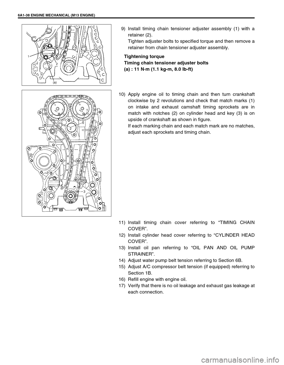
1) Turn steering wheel so that vehicle’s front tires are at
straight-ahead position.
2) Turn ignition switch to “LOCK” position and remove key.
3) Remove steering joint cover (5).
4) Make alignment marks (4) on lower shaft (1) and shaft joint
of steering column (2) and lower shaft (1) and pinion shaft
(3) for a guide during reinstallation.
5) Remove lower shaft joint bolts (6).
6) Remove steering lower shaft (1).
CAUTION:
Never turn steering wheel while steering lower shaft is
removed.
Should it have been turned and contact coil (on combina-
tion switch) have got out of its centered position, it needs
to be centered again. Also, turning steering wheel more
than about two and a half turns will break contact coil.
Page 537 of 698

6A1-36 ENGINE MECHANICAL (M13 ENGINE)
Timing chain No.1 guide
Check shoe (1) for wear or damage.
INSTALLATION
1) Check that match marks (1) on intake and exhaust camshaft
timing sprockets are in match with notches (2) on cylinder
head as shown in figure.
2) Set key (3) and turn crankshaft to position key on upside of
crankshaft.
3) Install timing chain by aligning dark blue plate (1) of timing
chain and triangle mark (2) on camshaft timing sprocket as
shown in figure.
4) Fit crankshaft timing sprocket to timing chain by aligning gold
plate (3) of timing chain and mark (4) on crankshaft timing
sprocket. Then install crankshaft timing sprocket fitted with
chain to crankshaft.
CAUTION:
After timing chain is removed, never turn crankshaft and
camshafts independently more than such an extent (“a”,
“b”) as shown in figure.
If turned, interference may occur between piston and
valves and valves themselves, and parts related to piston
and valves may be damaged.
“a” :90°4. Camshaft (IN and EX) allowable turning range.
By marks on camshaft timing sprocket within 15° from notches on
cylinder head on both right and left.
“b” :15°5. Crankshaft allowable turning range.
By key on crankshaft, within 90° from top on both right and left.
Page 539 of 698

6A1-38 ENGINE MECHANICAL (M13 ENGINE)
9) Install timing chain tensioner adjuster assembly (1) with a
retainer (2).
Tighten adjuster bolts to specified torque and then remove a
retainer from chain tensioner adjuster assembly.
Tightening torque
Timing chain tensioner adjuster bolts
(a) : 11 N·m (1.1 kg-m, 8.0 lb-ft)
10) Apply engine oil to timing chain and then turn crankshaft
clockwise by 2 revolutions and check that match marks (1)
on intake and exhaust camshaft timing sprockets are in
match with notches (2) on cylinder head and key (3) is on
upside of crankshaft as shown in figure.
If each marking chain and each match mark are no matches,
adjust each sprockets and timing chain.
11) Install timing chain cover referring to “TIMING CHAIN
COVER”.
12) Install cylinder head cover referring to “CYLINDER HEAD
COVER”.
13) Install oil pan referring to “OIL PAN AND OIL PUMP
STRAINER”.
14) Adjust water pump belt tension referring to Section 6B.
15) Adjust A/C compressor belt tension (if equipped) referring to
Section 1B.
16) Refill engine with engine oil.
17) Verify that there is no oil leakage and exhaust gas leakage at
each connection.
Page 543 of 698

6A1-42 ENGINE MECHANICAL (M13 ENGINE)
Wear of tappet and shim
Check tappet and shim for pitting, scratches or damage.
If any malcondition is found, replace.
Measure cylinder head bore and tappet outside diameter to deter-
mine cylinder head-to-tappet clearance. If clearance exceeds
limit, replace tappet or cylinder head.
Cylinder head to tappet clearance
Standard : 0.025 – 0.066 mm (0.0010 – 0.0026 in.)
Limit : 0.15 mm (0.0059 in.)
Tappet outside diameter [A]
Standard : 30.959 – 30.975 mm (1.2189 – 1.2195 in.)
Cylinder head tappet bore [B]
Standard : 31.000 – 31.025 mm (1.2205 – 1.2215 in.)
INSTALLATION
1) Install tappets and shims to cylinder head.
Apply engine oil around tappet and then install it to cylinder
head.
2) Install camshafts (1).
Apply engine oil to sliding surface of each camshaft and camshaft
journal then install them as shown in figure.
NOTE:
When installing shim, make sure to direct shim No. side
toward tappet.
NOTE:
Before installing camshafts, turn crankshaft until key
position faces upward. Refer to “TIMING CHAIN AND
CHAIN TENSIONER”.