Page 65 of 86

Downloaded from www.Manualslib.com manuals search engine FABIA 2000➤Inspection and Maintenance
Electrical SystemEdition 09.04
S00.5301.14.2002-6 page 11 02
Test and setting conditions
•Tyre inflation pressure O.K.
•Lenses must neither be damaged nor soiled.
•Reflectors and bulbs O.K.
•Vehicle load must be achieved.
Load: With an individual or 75 kg on the driver's seat in an
otherwise unladen vehicle (dead weight).
The unladen weight is the weight of the vehicle with full
fuel tank (at least 90 %) including the weight of all the op-
erational equipment elements (e.g. spare wheel, tool kit,
jack etc.).
The vehicle must have rolled a few metres or have been
depressed a few times at the front and rear to allow the
springs to settle.
•Both the vehicel and headlight beam setting device
must be on a level flat surface.
•Align the vehicle and headlight beam setting device in
accordance with the device manufaturer's indications.
•Check the control system of vehicles equipped with
headlight beam control by repeatedly turning the
thumbwheel in the dash panel. Then turn the thum-
bwheel to basic position.
•Set the inclination value.
Inclination value:
The inclination value is marked in „%“ at the top of the
headlight housing. The main headlights must be set to
this value. The percentage value applies up to 10 metres
projection distance. This will be 12 cm for an inclination
value of e.g. 1.2 %.
Inspecting headlight beam setting and adjusting
if necessary
Main headlights:
–Check whether the horizontal light/dark limit touches
the separation mark -1- on the test surface when the
low beam light is on .
–Check whether the kink -2- between the left horizontal
part and the ascending right part of the light/dark limit
intersects with the central mark -3- on the vertical line.
The light core of the light beam must be located to the
right of the vertical line.132
S02-0091
Page 66 of 86

Downloaded from www.Manualslib.com manuals search engine FABIA 2000➤Inspection and Maintenance
Electrical SystemEdition 09.04
S00.5301.14.2002-6 page 12 02
♦To easily determine the kink -2-, alternately cover and
uncover the left half of the headlight (in the driving di-
rection) a few times. After this, check the low beam
once again.
♦Once the low beam light has been correctly set the
centre of the light beam of the main beam must be po-
sitioned on the central mark -3-.
♦The adjustment foreseen for the new control screen
also applies for the previous one, which has a 15 ad-
justing line. To avoid incorrect settings disregard the
15 adjusting line.
Other additional headlights:
Additionally fitted headlights must be inspected or set in
compliance with the relevant applicable directives.
Setting the headlight beam
Setting the main beam
The headlight adjusting device is used to set up the head-
light. Nominal values ⇒02-6 page 10.
Left headlight (right headlight in mirror image)
1 - Vertical adjustment
2 - Lateral adjustment
–Adjust with corresponding thumbwheel.
Adjust the fog light beam
Inclination value:
The angle is 2.2%.
Vehicles up to MY 2004
Right fog light (left fog light in mirror image)
Note
S02-0090
Note2
1
S94-0095
1
2
S94-0103
Page 67 of 86
Downloaded from www.Manualslib.com manuals search engine FABIA 2000➤Inspection and Maintenance
Electrical SystemEdition 09.04
S00.5301.14.2002-6 page 13 02
Vehicles as MY 2005
Left fog light (right fog light in mirror image)
–Unclip the cap -1- on the bumper.
–Use a screwdriver to turn screw -2- and to align the fog
light beam.
Vehicles RS
Left fog light (right fog light in mirror image)
–Unclip the cap -1- on the bumper.
–Use a screwdriver to turn screw -2- and to align the fog
light beam.
Replace emergency battery for alarm
system
–Replacing the alarm of the alarm system ⇒Electrical
System; Rep. Gr. 94.
Page 68 of 86
Downloaded from www.Manualslib.com manuals search engine FABIA 2000➤Inspection and Maintenance
Electrical SystemEdition 09.04
S00.5301.14.2002-6 page 14 02
Page 69 of 86

Downloaded from www.Manualslib.com manuals search engine FABIA 2000➤Inspection and Maintenance
BodyEdition 09.04
S00.5301.14.2002-7 page 1 02
02-7 Body
Airbag units: Visual inspection
Inspecting operation of airbag unit
When the ignition is switched on the airbag warning lamp
K75 lights up for approximately 4 seconds. Should the
warning lamp flash again for a further 12 seconds this is
an indication that the front passenger airbag or the side
airbag unit on the front passenger is electronically locked
(valid for vehicles which do not have an airbag switch-off
function).
The warning lamp will go out after 4 seconds for vehicles
which are fitted with an airbag switch-off function and
switching off of the front passenger airbag will be sig-
nalled by the warning lamp „AIRBAG OFF“ in the middle
of the dash panel.
♦If warning lamp K75 does not go out after 4 seconds
and lights up continously there is a fault.
♦If the warning lamp goes out and then lights up again
the control unit is not coded, the wrong control unit has
been fitted or there is a fault.
♦If the airbag warning light K75 flashes constantly, it is
then necessary to replace the airbag control unit J234.
If the warning light indicates a fault, the fault must be
rectified (repair measure) Body Work; Rep. Gr. 01.
Inspecting airbag for external damage
Driver and front passenger airbag units
The logo „AIRBAG“ on the padded boss of the steering
wheel (driver's side) and on the right side of the dash pan-
el (passenger side) indicates that an airbag is fitted.
–Carry out a visual inspection of the padded boss of the
steering wheel -1- and surface of the dash panel -2-
on the front passenger side for external damage.
–Undertake a visual inspection of the front seats to de-
termine any damage (valid for vehicles with side air-
bags).
♦Only use original seat upholstery approved for side
airbags.
♦The use of commercially available protective seat cov-
ers is prohibited as this impairs the operation of the
side airbags.
♦Replace all harpoon clips with new original parts.
♦In the event of damage to the upholstery - tears, burn
holes etc. - in the area of the side airbag always re-
place the upholstery with a new original part for safety
reasons.
1
S02-0297
2
Page 70 of 86

Downloaded from www.Manualslib.com manuals search engine FABIA 2000➤Inspection and Maintenance
BodyEdition 09.04
S00.5301.14.2002-7 page 2 02
Do not affix any stickers or cover over the padded boss of
the steering wheel -1- and the foam-lined surface of the
airbag unit on the front passenger side -2- or do not carry
out any modifications to these parts. These parts must
only be cleaned with a dry and slightly moistened cloth.
Inspect key switch for deactivation of
front passenger airbag
–Switch off ignition.
–Turn the key switch for deactivation of front passenger
airbag to the position „OFF“.
When the ignition is switched on the airbag warning lamp
must light up in the front interior light.
–Switch off ignition.
–Turn the key switch for deactivation of front passenger
airbag to the position „ON“.
After the ignition and the front passenger airbag is
switched on, the airbag warning light in the front interior
light must no longer light up after approx. 3 seconds.
Key switch for deactivation of front passenger airbag
must only be turned when ignition is switched off. If the
position of the switch is changed, the airbag control unit
can evaluate a fault; the individual contacts in the switch
make contact during different time intervals and subse-
quently the warning lamp lights up in the dash panel in-
sert (there is no risk of airbag activation).
Check underbody protection and body
paintwork for damage
The inspection of the underbody sealant and paintwork
should cover the following points:
1) undamaged layer of PVC Plastisol
–Vehicle floor
–Wings and wheel housings
–Sills
2) undamaged paintwork
–all body joints
–surround of windscreen
–surround of rear window
–flange of inner surfaces of engine hood
–horizontal and vertical painted surfaces
–Connection of the roof in the area of the luggage com-
partment lid
It is essential to rectify any defects found!
Note
Note
Page 71 of 86

Downloaded from www.Manualslib.com manuals search engine FABIA 2000➤Inspection and Maintenance
BodyEdition 09.04
S00.5301.14.2002-7 page 3 02
The materials and the corresponding work instructions
are listed in the ⇒Technical Service Handbook, Part 6 -
Technology of paint repairs, chemical materials.
Inspecting plenum chamber and water
drain openings for dirt, cleaning if neces-
sary
Carry out a visual inspection for soiling through the cover
of the plenum chamber -arrows-. Remove the cover if it is
necessary to clean the plenum chamber (repair meas-
ure).
The water drain openings must not be blocked with wax
or underbody sealant.
Windscreen wiper/washer system:
Check for proper operation
Fluid in windscreen washer fluid reservoir
The fluid reservoir for the windscreen washer system
must be filled up to the brim.
♦If it is necessary to add fluid, always mix windscreen
cleaner to the water (in summer) or antifreeze agent
(in the winter).
♦If the vehicle is fitted with a headlight washing system
and the headlights have plastic - (polycarbonate) -
lenses, one must only use fluids for topping up the
headlight washing system which do not damage the
polycarbonate.
Inspecting setting of nozzles of windscreen
washer system, adjusting nozzles if necessary:
Nozzles of windscreen washer system
The nozzles on the windscreen washer system are set by
the manufacturer and cannot be subsequently altered.
–The water spray should strike the windscreen in a
cone-shaped pattern.
If the spray flows out unevenly, replace the spray nozzle
(repair measure).
Windscreen wiper arms: Inspecting park posi-
tion, adjusting if necessary
–Wiper arms are positioned relative to the round mark-
ings in the windscreen.
S02-0298
Note
Note
S02-0300
Note
Page 72 of 86

Downloaded from www.Manualslib.com manuals search engine FABIA 2000➤Inspection and Maintenance
BodyEdition 09.04
S00.5301.14.2002-7 page 4 02
The specified tightening torque for the windscreen wiper
arms is 20 Nm.
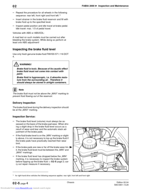
Wiper arms of rear window: Inspecting park po-
sition, adjusting if necessary, spray nozzle of
rear window: Inspect setting and adjust if neces-
sary
The spray should strike the rear window as shown in the
illustration when the vehicle is stationary.
–Set the position of the windscreen wiper arm in such a
way that it is parallel to the edge of the ceramic
sprayed film (on vehicles with spray nozzles in the
windscreen wiper arm).
The spray should strike the rear window as shown in the
illustration when the vehicle is stationary.
–Set the position of the windscreen wiper arm in such a
way that it is parallel to the edge of the ceramic
sprayed film (on vehicles with spray nozzles in the ad-
ditional brake light).
The specified tightening torque for the windscreen wiper
arms is 12 Nm.
–Inspect setting of nozzle, if necessary adjust with a
tool, e.g. with a needle.
If the spray flows out unevenly, or if it cannot be adjusted,
replace the spray nozzle (repair measure).
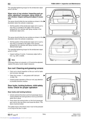
Sun roof: Cleaning and greasing runners
–Carry out a visual inspection of the sun roof for leaks
and corrosion damage
–Clean the runners -1- and grease with lubricant
-G 052 778-.
–Inspect proper operation of the sun roof, pay attention
to possible abrasive residue.
Door locks, locking buttons, child safety
locks: Check for proper operation
Door locks and locking buttons:
–Unlock and lock the driver and front passenger doors.
Check whether the locking buttons move up and down
when this is done.
–Press down the locking button on the front passenger
door and on the rear doors and close the doors. The
doors must be locked.
The safety knob on the driver's door must not be pressed
in as long as the door is open.
S02-0304
Note
S02-02431