Page 21 of 118
Downloaded from www.Manualslib.com manuals search engine ENGINE AND PERIPHERALS
Engine and transmission assembly
10
10-5
– the closure panel for the plenum chamber.
Remove (all types):
– the shock absorber cap protectors,
– the clutch cable,
– the brake servo vacuum pipe,
– the air intake pipe,
– the turbocharging air ducts between the exchanger
and the engine,
– the hoses on the heater radiator,
– the pipes (6) and the connectors (7),– the battery mounting,
– the expansion bottle mountings and the expansion
bottle,
– the precatalytic converter mountings and the
precatalytic converter,
– the relay plate at (1) and the fuse holder (2) as well
as the connectors (3) and (4),
– the injection computer connectors (8),
– the earth strap (9),
– the fuel pipes (10) and fit cleanliness plugs.
11036R2
16869R
16872R
16870R
Page 22 of 118
Downloaded from www.Manualslib.com manuals search engine ENGINE AND PERIPHERALS
Engine and transmission assembly
10
10-6
– the earth strap on the bulkhead,
– the mountings of the air conditioning hoses (if
fitted) on the compressor and the condenser.
NOTE: it is essential to insert plugs in the pipes and on
the compressor to prevent the moisture entering the
circuit.
Remove the upper radiator mountings and attach the
cooling system to the engine.
Fit the engine retaining tool Mot. 1453 ensuring that
the strap is correctly positioned.
Remove the suspended engine mounting cover.Insert a wooden block between the gearbox and the
sub-frame.
Remove the nut (1), then tap it with a copper hammer
to release the suspended engine mounting stud.
Fit tool Mot. 1159 as shown below.
13932R
17518R1
17518R2
99024R2
Page 24 of 118

Downloaded from www.Manualslib.com manuals search engine ENGINE AND PERIPHERALS
Sump
10
10-8
Sump
SPECIAL TOOLING REQUIRED
Mot. 1233-01 Threaded rods for lowering the
sub-frame
REMOVAL
Put the vehicle on a two post lift.
Disconnect the battery.
Remove the engine undertray.
Drain the engine.
Remove:
– the front wheels as well as the right hand mudguard
and the lower clip of the left hand mudguard,
– the nut and the eccentric bolt of the steering shaft
yoke, after pushing back the guard.Remove:
– the lower ball joint mountings as well as the track rod
ends,
– the sub-frame and body tie rods,
– the gear control on the gearbox side,
– the horn,
– the bolt (1), and slacken engine tie-bar bolt (2),
without removing it,
– the bottom mountings of the bumper, TIGHTENING TORQUES (n daN.m)
Sub-frame front mounting bolts 6.2
Sub-frame rear mounting bolts 10.5
Sump bolts 1.5
Steering shaft yoke mounting bolt 3
Lower ball joint mounting bolt 6
Engine tie bar bolt 6.2
Sub-frame - side member tie rod bolts 3
Wheel bolts 9
WARNING
In order to eliminate any risk of damaging the
rotary switch under the steering wheel, observe
the recommendations below:
!Before the steering column and the steering
rack are uncoupled, the steering wheel MUST
be immobilised with the wheels straight for the
duration of the operation using a "steering
wheel locking tool".
!If there is any doubt regarding the correct
alignment of the rotary switch, the steering
wheel must be removed so that the alignment
procedure described in the "AIRBAG" section
can be applied.
REMINDER: in this case, only qualified
personnel who have received training may carry
out the operation.
17518R3
Page 28 of 118

Downloaded from www.Manualslib.com manuals search engine TOP AND FRONT OF ENGINE
Timing belt
11
11 - 2
Special features of vehicles fitted with air
conditioning:
Before removing the accessories belt, check the
centreline of the automatic tensioner (see
section 07 "Checking the accessories belt
tension").
Loosen bolt (A), then bolt (B) to past the shoulder
while holding the automatic tensioner plate using a
9.35 mm square, then relax the belt moving the
ratchet in the direction of the arrow.
Remove the Top Dead Centre pin plug.
Position the engine support, tool Mot. 1453 with the
retaining straps.Remove:
– the suspended mounting cover and its movement
limiter.
– the bolt (1), and slacken engine tie-bar bolt (2),
without removing it.
Adjusting the timing
Turn the crankshaft to align the camshaft and housing
timing marks while at the same time inserting the TDC
pin Mot. 1054 (begin to press one half tooth on the
pin before aligning the camshaft marks to prevent
it falling into a crankshaft balancing hole).
98837-1R4
13932R
17518R3
12518R2
Page 31 of 118

Downloaded from www.Manualslib.com manuals search engine TOP AND FRONT OF ENGINE
Timing belt
11
11 - 5
Fit the reading head of Mot. 1505 and carry out the
measurement, then adjust the tension using the bolt
in contact with the belt until pretension value
T1 = 68 ± 3 Hertz is reached.
Tighten the tensioner.
Turn the crankshaft four times and reposition the
timing at top dead centre using the pin.
Remove pin Mot. 1054.
Apply a pretensioning torque using Mot. 1543 (fitted
with cover N˚ 3) by using a torque wrench adjusted to
a torque of 1.1 daN.m on the edge of the belt to be
measured.
Fit the reading head of Mot. 1505 and carry out the
measurement, then adjust the tension using the bolt
in contact with the belt until pretension value
T2 = 61 ± 5 Hertz is reached.
Tighten the tension wheel nut to a torque of 5 daN.m.
NOTE: it is vital that you tighten the tension wheel
nut to torque to avoid any slackening which may
cause damage to the engine.
Never refit a belt once removed, but replace it.
Replace the crankshaft pulley bolt and tighten it to a
torque of 2 daN.m plus an angle of 115˚ ± 15˚.
See section 07 "Accessories belt tension" for the
tension value for fitting the power assisted steering
belt.The belts on vehicles fitted with air conditioning are
tensioned by bringing the automatic tensioner plate to
a stop at bolt (B), without forcing it, using a 9.35 mm
square.
98837-1R1
Page 34 of 118
Downloaded from www.Manualslib.com manuals search engine TOP AND FRONT OF ENGINE
Cylinder head gasket
11
11 - 8
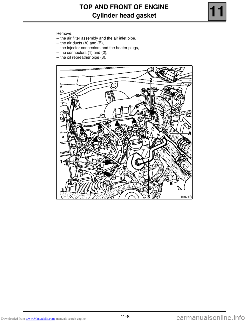
Remove:
– the air filter assembly and the air inlet pipe,
– the air ducts (A) and (B),
– the injector connectors and the heater plugs,
– the connectors (1) and (2),
– the oil rebreather pipe (3),
16871R
Page 39 of 118
Downloaded from www.Manualslib.com manuals search engine FUEL MIXTURE
Air intake
12
112
FUEL MIXTURE
Air intake
AIR INTAKE CIRCUIT DIAGRAM
1 Air-air exchanger
2 Air filter
3 Flow meter
4 Inlet manifold
5 Turbocharger
A Air inlet
12-1
Page 41 of 118

Downloaded from www.Manualslib.com manuals search engine TURBOCHARGING
Pressure adjustment
12
12-3
Pressure adjustment
TURBOCHARGING PRESSURE LIMITATION
VALVE (WASTEGATE)
NB: the limitation valve operates in the opposite
way to the usual fittings.
The absence of control pressure causes a
turbocharging pressure limitation.
Check that there are no leaks between the vacuum
pump and the limitation valve.
Checking calibration pressure
Fit on vehicle.
Use a dial gauge which should be positioned at the
end of the wastegate rod (as far as possible in the
wastegate axis).
An underpressure is progressively generated on the
wastegate using a manual vacuum pump.Calibration values
Fitting on the vehicle
When checking the calibration pressure it may be
necessary to adjust the wastegate rod length (A) (if
the pressure is not within tolerance).
This adjustment is made with the turbocharger in
place.
Loosen the lock nut then loosen or tighten the
adjusting nut (B).
Validate the repair in a road test, checking the "RC0
turbocharging limiter valve" parameters and the
"turbocharging pressure" on the diagnostic tools.
17827S
Underpressure
valuesRod movement
(mm)
120 mb Between 1 and 4 mm
400 mb Between 10 and 12 mm
> 450 mb Rod at stop
17827-1R3