Page 43 of 118
Downloaded from www.Manualslib.com manuals search engine TURBOCHARGING
Turbocharger
12
12-5
From above
Remove (for the Scénic):
– the windscreen wiper arms using tool Elé. 1294-01,
– the scuttle panel,
– the bulkhead panel,
Disconnect the flow meter and remove the air unit.Remove:
– the turbo oil inlet connection (4),
– the two air intake and outlet ducts connected to the
turbo,
– the two upper turbo mounting nuts on the manifold.
Disconnect the rubber hose (9) (connected to the
wastegate).
11020R
11036R2
12415R6
Page 44 of 118
Downloaded from www.Manualslib.com manuals search engine TURBOCHARGING
Turbocharger
12
12-6
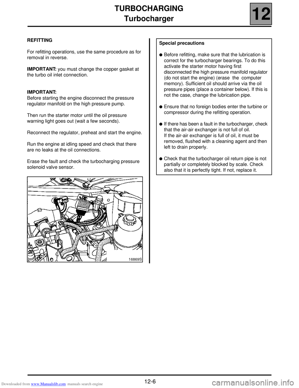
REFITTING
For refitting operations, use the same procedure as for
removal in reverse.
IMPORTANT: you must change the copper gasket at
the turbo oil inlet connection.
IMPORTANT:
Before starting the engine disconnect the pressure
regulator manifold on the high pressure pump.
Then run the starter motor until the oil pressure
warning light goes out (wait a few seconds).
Reconnect the regulator, preheat and start the engine.
Run the engine at idling speed and check that there
are no leaks at the oil connections.
Erase the fault and check the turbocharging pressure
solenoid valve sensor.
16869S
Special precautions
!Before refitting, make sure that the lubrication is
correct for the turbocharger bearings. To do this
activate the starter motor having first
disconnected the high pressure manifold regulator
(do not start the engine) (erase the computer
memory). Sufficient oil should arrive via the oil
pressure pipes (place a container below). If this is
not the case, change the lubrication pipe.
!Ensure that no foreign bodies enter the turbine or
compressor during the refitting operation.
!If there has been a fault in the turbocharger, check
that the air-air exchanger is not full of oil.
If the air-air exchanger is full of oil, it must be
removed, flushed with a cleaning agent and then
left to drain properly.
!Check that the turbocharger oil return pipe is not
partially or completely blocked by scale. Check
also that it is perfectly tight. If not, replace it.
Page 45 of 118
Downloaded from www.Manualslib.com manuals search engine TURBOCHARGING
Air-air exchanger
12
12-7
Air-air exchanger
REMOVAL
It is necessary to remove the bumper to access the air-
air exchanger.
To do this, remove:
– the two upper side mounting bolts (A) (torx 20) and
the lower side mounting bolt (B) (torx 20) from the
front section of the front wing inner protector,
– the three mounting clips (C),
– the mounting clip (D) and separate the front section
of the right and left wing protector.If the vehicle is fitted with fog lights.
Disconnect:
– the battery,
– the fog light wiring harness connector (E) located in
the front section of the left-hand front wheel arch.
Remove:
– the upper side mounting bolt (F) on the bumper (on
each side),
– the two front engine underbody mounting bolts,
98710R2
99184R
99147R
Page 46 of 118
Downloaded from www.Manualslib.com manuals search engine TURBOCHARGING
Air-air exchanger
12
12-8
– the central mounting bolt (torx 40).
Remove the two side positioning centring fittings on
the bumper in relation to the wing.
Remove:
– the bumper by pulling forwards,– the flexible air inlet and outlet ducts on the
exchanger (1),
– three mounting bolts,
– the air-air exchanger.
REFITTING
Refit the unit proceeding in the reverse order to
removal.
98836-1R1
99301R94965R
10320R
Page 47 of 118
Downloaded from www.Manualslib.com manuals search engine FUEL MIXTURE
Manifolds
12
12-9
FUEL MIXTURE
Manifolds
REMOVAL
NOTE: Removal of the manifolds requires that you
remove the turbocharger (see section 12
"Turbocharging"). The two manifolds cannot be
removed separately.
Disconnect:
– the battery,
– the air inlet pipe from the intake manifold (2),
– the pipe leading to the pressure sensor on the
manifold (1),
– the EGR (5) solenoid valve.Remove (for the Scénic):
– the windscreen wiper arms,
– the scuttle panel,
– the bulkhead panel,
– the air unit,
– the turbocharger. TIGHTENING TORQUES (in daN.m )
Manifold mounting stud 0.8
Manifold mounting stud 2.8
EGR valve mounting bolt 2.1
16869R2
12415R1
Page 50 of 118
Downloaded from www.Manualslib.com manuals search engine FUEL MIXTURE
Priming catalytic converter
12
12-12
Priming catalytic converter
REMOVAL
Put the vehicle on a two post lift.
Disconnect the battery.
Remove the cover and the under body protection.
Disconnect the exhaust downpipe.Remove (for the Scénic) :
– the windscreen wiper arms using tool Elé. 1294-01,
– the scuttle panel,
– the bulkhead panel,
Disconnect the flow meter and remove the air unit.
Remove:
– the priming catalytic converter mounting stay,
– the mounting nuts,
– the pre-catalytic converter. TIGHTENING TORQUES (in daN.m )
Priming catalytic converter mounting nuts
(pre-catalytic converter) 2.4
Lower mounting bolt 2.4
Priming catalytic converter stay bolt 6
16156S
11020R
11036R2
Page 52 of 118

Downloaded from www.Manualslib.com manuals search engine DIESEL EQUIPMENT
Specifications
13
113
DIESEL EQUIPMENT
Specifications
Vehicle GearboxEngine
Depollution
standard
Type IndexBore
(mm) Stroke
(mm) Cubic
capacity
(cm
3)Compres-
sion ratioCatalytic
converter
XA05 JC5 F9Q 732 80 93 1 870 19/1◊ C103 Euro 2000
ENGINE SPEED (rpm) SMOKE DENSITY
IDLING SPEED Max. - no loadMax. - under
loadHomologation value Max. - Max
835 ± 50 4,700 ± 150 4,500 ± 100
1.5 m
-1 (46 %) 3 m-1 (70 %)
DESCRIPTION BRAND/TYPE SPECIAL NOTES
High pressure pumpBOSCH
CR/CP153/R65/10-15Pressure from 250 to 1350 bars
Supercharging pump (low
pressure)BOSCHPressure from 2.5 to 4 bars
Flow: 80 to 100 litres/hour minimum
Diesel pressure sensor BOSCHFitted to the injection rail
Resistance: tracks 1,2 and 1,3 = 4.3 MΩ
tracks 2,3 = 1050 Ω
Injectors BOSCHSolenoid injector
Resistance: < 2 Ω
Maximum pressure 1525 bars
Pressure regulator - Integrated with the high pressure pump
Resistance: ≈ 5 Ω at 20˚ C
Injection computer BOSCH128 track computer
Pre-postheating unit NAGARES BED/7With pre-postheating function controlled by the
injection computer
Heater plugsBERU
or
CHAMPIONResistance: 0.6 Ω connector removed
Accelerator potentiometer CTSDouble track potentiometer
Track resistance ≈ 1.7 Ω
Air intake temperature sensor SIEMENSintegrated in the flow meter
Resistance between 100 Ω and 40 Ω
13-1
Page 53 of 118

Downloaded from www.Manualslib.com manuals search engine DIESEL EQUIPMENT
Specifications
13
13-2
DESCRIPTION MAKE/MODEL SPECIAL NOTES
Diesel temperature sensorMAGNETTI
MARELIResistance: ≈ 2.050 Ω at 25 ˚C
Engine speed sensor MGI Resistance: 800 ± 80 Ω
Atmospheric pressure sensor - Integrated in the computer
Camshaft sensor ELECTRIFIL Hall effect sensor
Turbocharger pressure sensor DELCOResistance : 4 KΩ across tracks A and C
Resistance : 5 KΩ across tracks A and C
Resistance : 9 KΩ across tracks A and B
Turbocharger operating
solenoidBITRON Resistance 16.5±1 Ω at 25 ˚C
Air flow meter SIEMENSFlow meter with integrated air temperature sensor
track 1 : air temperature
track 2 : earth
track 3 : 5 V reference
track 4 : + battery feed
track 5 : air flow signal
track 6 : earth
EGR solenoid valve PIERBURGTrack resistance: 8±0.5 Ω to 20 ˚C (tracks 1 and 5)
Sensor resistance: 4 KΩ to 20 ˚C (tracks 2 and 4)
Turbocharger KKKCalibration :
120 mbars for rod travel between 1 and 4 mm
400 mbars for a stroke between 10 and 12 mm
Thermal plungers - Resistance: 0.45 ± 0.05 Ω at 20 ˚C


