Page 97 of 118

Downloaded from www.Manualslib.com manuals search engine ANTIPOLLUTION
Exhaust gas recirculation
14
14-3
OPERATING PRINCIPLE
The valve is controlled by an RCO signal issued by the
injection computer. The RCO signal permits
modulation of the opening of the valve, and
consequently, the quantity of exhaust gas directed
back towards the inlet manifold.
The computer continuously carries out a test to detect
the position of the EGR valve flap.
OPERATING CONDITIONS
The parameters which determine the actuation of the
EGR valve are as follows:
– the coolant temperature,
– the air temperature,
– the air pressure,
– the accelerator pedal position,
– the engine speed.
The EGR function is cut if:
– the battery voltage is less than 9 volts,
– the engine speed is greater than 3000 rpm.,
– a characteristics map (engine speed/load) exceeds a
given threshold,
– the vehicle speed is less than 12 km/h, the engine
speed is less than 1000 rpm and if the coolant
temperature is greater than 60 ˚C for 40 seconds.
The EGR valve is not supplied after engine start
according to a coolant temperature characteristics
map.
time (s)The electric EGR valve is supplied for 40 seconds on
each return to idling speed if the air temperature is
greater than 15 ˚C.
Coolant
temperature (˚C)
15761R
1
2
4
5
6Solenoid supply
Sensor supply
Sensor earth
Solenoid earth
Sensor output
-20 0 17 20
Page 98 of 118
Downloaded from www.Manualslib.com manuals search engine STARTING - CHARGING
Alternator
16
116STARTING - CHARGING
Alternator
IDENTIFICATION
CHECKING
After 15 minutes warming up at a voltage of 13.5 volts. Type Engine Alternator Current
XA0 5 F9Q 732
SG 10 B010
SG 10 B011
A13VI252
A11VI88120 A
80 A
75 A
Rpm. 75 Amps 80 Amps 120 Amps
1 000 40 54 -
1 500 - - 26
2 000 68 75 -
3 000 71 80 -
4 000 72 82 94
6 000 - - 105
16-1
Page 99 of 118

Downloaded from www.Manualslib.com manuals search engine STARTING - CHARGING
Alternator
16
16-2
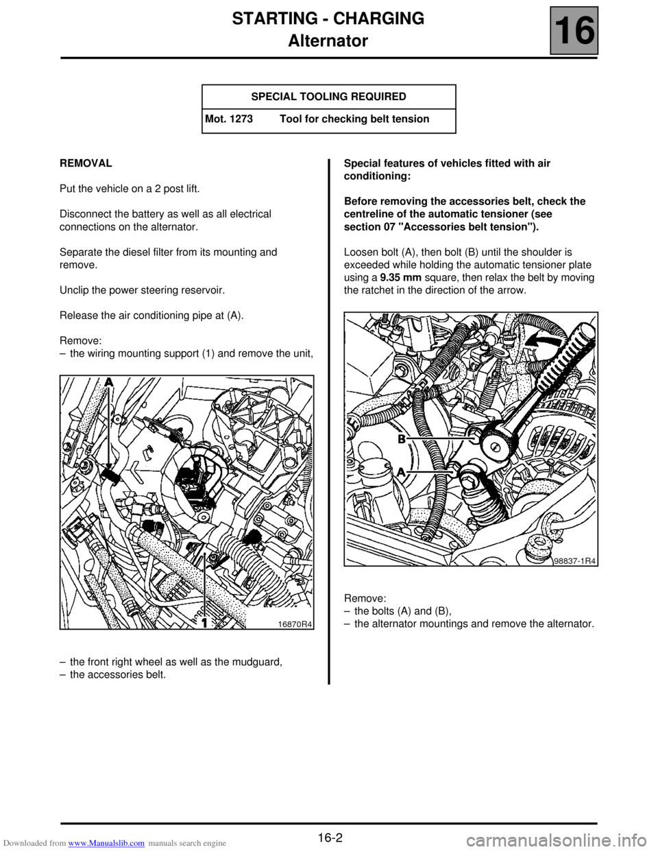
REMOVAL
Put the vehicle on a 2 post lift.
Disconnect the battery as well as all electrical
connections on the alternator.
Separate the diesel filter from its mounting and
remove.
Unclip the power steering reservoir.
Release the air conditioning pipe at (A).
Remove:
– the wiring mounting support (1) and remove the unit,
– the front right wheel as well as the mudguard,
– the accessories belt.Special features of vehicles fitted with air
conditioning:
Before removing the accessories belt, check the
centreline of the automatic tensioner (see
section 07 "Accessories belt tension").
Loosen bolt (A), then bolt (B) until the shoulder is
exceeded while holding the automatic tensioner plate
using a 9.35 mm square, then relax the belt by moving
the ratchet in the direction of the arrow.
Remove:
– the bolts (A) and (B),
– the alternator mountings and remove the alternator. SPECIAL TOOLING REQUIRED
Mot. 1273 Tool for checking belt tension
16870R4
98837-1R4
Page 100 of 118
Downloaded from www.Manualslib.com manuals search engine STARTING - CHARGING
Alternator
16
16-3
REFITTING (special notes)
Refit in reverse order to removal.
The belts on vehicles fitted with air conditioning are
tensioned by bringing the automatic tensioner plate to
a stop at bolt (B), without forcing it, using a 9.35 mm
square.
See section 07 "Accessories belt tension" for the
belt tension value for vehicles without air conditioning.
NOTE: never refit a belt once it has been removed,
but replace it.
98837-1R1
Page 101 of 118
Downloaded from www.Manualslib.com manuals search engine STARTING - CHARGING
Starter
16
16-4
Starter
IDENTIFICATION
Type Engine Starter motor
XA0 5 F9Q 732 MITSUBISHI M1T85781
Page 102 of 118
Downloaded from www.Manualslib.com manuals search engine STARTING - CHARGING
Starter
16
16-5
REMOVAL
Put the vehicle on a 2 post lift.
Disconnect the battery.
Remove (for the Scénic):
– the front right hand grille as well as the mounting
bolts of the left hand grille,
– the closure panel of the scuttle,Remove (all types):
– the turbocharging air ducts between the exchanger
and the engine,
– the pre-catalytic converter mountings to the turbo.
Loosen the exhaust pipe clamp mounting.
Remove:
– the pre-catalytic converter stay (1),
– the catalytic converter mountings on the precatalytic
converter and remove this by moving the engine
towards the cooling system,
– the oil return pipe (8),
– the starter electrical connections.
– the starter mountings,
– the starter motor.
REFITTING
To remove, proceed in the reverse order.
Check the presence of the starter motor centring
dowel.
11020R
11036R2
16155R
Page 103 of 118
Downloaded from www.Manualslib.com manuals search engine COOLING SYSTEM
Filling and bleeding
19
119 COOLING SYSTEM
Filling and bleeding
There is no heater matrix water control valve.
Water flow is continuous in the heater matrix, which
contributes to the cooling of the engine.
FILLING
It is essential to open the bleed screw on the
cylinder head coolant pipe housing outlet.
Fill the circuit through the expansion bottle opening.
Close the bleed screw as soon as the fluid runs out in
a continuous jet.
Start the engine (2500 rpm).
Adjust the level by overflow for a period of about
4 minutes.
Tighten the expansion bottle cap.
BLEEDING
Let the engine run for 20 minutes at 2500 rpm, until
the engine cooling fan operates (time required for
automatic degassing).
Check the liquid level is at the "Maximum" marker.
DO NOT OPEN THE BLEED SCREW(S) WITH THE
ENGINE RUNNING.
REFIT THE EXPANSION BOTTLE CAP WHILE THE
ENGINE IS WARM.
19-1
Page 104 of 118
Downloaded from www.Manualslib.com manuals search engine COOLING SYSTEM
Diagram
19
19-2
Diagram
1 Engine
2 Radiator
3 "Hot" container with degassing after thermostat
4 Heater matrix
5 Thermostat mounting
6 Thermoplunger mounting (if fitted)7 3 mm ∅ restriction
8 6 mm ∅ restriction
9 Oil/water exchanger
10 Water pump
11 Thermostat
12 Bleed screw
The expansion bottle valve rating is 1.2 bar
(colour: brown).