Page 8 of 118

Downloaded from www.Manualslib.com manuals search engine VALUES AND SETTINGS
Tightening the cylinder head
07
07-5
Tightening the cylinder head
METHOD FOR TIGHTENING THE CYLINDER HEAD
REMINDER: in order to tighten the bolts correctly, use
a syringe to remove any oil which may have entered
the cylinder head mounting bolt holes.
All the cylinder head bolts must always be changed
after removal. There is no cylinder head retightening
operation.
Preseating the gasket
Tighten all the bolts to 3 daN.m, then angle tighten to
100˚ ± 4˚ in the order shown below.
Wait 3 minutes settling time.
Tightening the cylinder head:
– cylinder head tightening is carried out in stages, and
the following procedure is applied successively to
bolts 1-2 then 3-4, 5-6, 7-8 and 9-10,
– slacken bolts 1-2 until they are completely free,
– tighten bolts 1-2 to 2.5 daN.m, then angle tighten to
213 ± 7˚,
– repeat the slackening and tightening operations for
bolts 3-4, 5-6, 7-8 and 9-10.
There is no cylinder head retightening operation.
90775S
Page 56 of 118

Downloaded from www.Manualslib.com manuals search engine DIESEL EQUIPMENT
Special notes
13
13-5
POST-REPAIR CHECK
A fuel cock is fitted to the fuel filter at the level of the diesel return pipe leading to the tank. It should be in open
position for normal operation.
However, to carry out a circuit reignition after an intervention, a filter change or a fuel fault, you should:
– close the fuel cock,
– start the low pressure pump by switching on the ignition several times,
– start the engine,
– OPEN THE FUEL COCK (the valve is open when the two coloured lines are aligned).
NOTE: certain vehicles are not fitted with a fuel cock. In this case, ignore this operation.
IMPORTANT: the engine must not run with diesel containing more than 10 % diester.
The system can inject the diesel into the engine up to a pressure of 1350 bars. Before any intervention, check
that the injector rail is depressurised.
It is absolutely vital that you observe the tightening torque:
– of the high pressure pipes,
– of the injector on the cylinder head,
– of the pressure regulator,
– of the pressure sensor.
When the high pressure pump, injectors, supply, return and high pressure output unions are repaired or
removed, the bores should be fitted with new and appropriate core seals to avoid impurities.
When replacing a high pressure pipe, the following procedure should be observed:
– remove the high pressure pipe,
– fit the cleanliness plugs,
– loosen the high pressure rail and the pump/rail pipe,
– fit the high pressure pipe,
– tighten the injector side union to torque,
– tighten the connection on the high pressure pump side to torque,
– tighten the high pressure rail fastenings to torque.
– tighten the pump/rail pipe to torque (pump side first).
It is prohibited to remove the interior of the pump.
It is vital that you replace the fuel return pipe placed on the injectors during removal.
The diesel temperature sensor is not removable. It is part of the fuel return rail.
It is forbidden to loosen a high pressure pipe connection when the engine is running.After any operation, check that there are no diesel leaks. Start the engine at idling speed until the fan starts up,
then accelerate several times under no load.
Page 72 of 118
Downloaded from www.Manualslib.com manuals search engine DIESEL EQUIPMENT
Low pressure pump (supercharging pump)
13
13-21
Low pressure pump (supercharging pump)
The supercharging pump is an electric pump located in
the engine compartment.
REMOVAL
IMPORTANT: take note of the quantity of diesel and
the residual pressure in the pipes.IMPORTANT:
A fuel cock (R) is fitted to the fuel filter at the level of
the return pipe leading to the tank.
It should be in open position for normal operation.
To reprime the circuit after an intervention, a filter
change or a fuel fault you should:
– close the fuel cock (R),
– start the low pressure pump by switching on the
ignition several times,
– start the engine,
– OPEN THE FUEL COCK (the valve is open when the
two coloured lines are aligned).
NOTE: certain vehicles are not fitted with a fuel cock.
In this case, ignore this operation. YOU SHOULD FOLLOW THE CLEANNESS
INSTRUCTIONS CLOSELY.
16776S
16870R3
Page 73 of 118

Downloaded from www.Manualslib.com manuals search engine DIESEL EQUIPMENT
Fuel filter
13
13-22
Fuel filter
The fuel filter is located in the engine compartment. It is contained in an unremovable cartridge. This cartridge
contains a regulating valve which limits the flow of diesel circulating to the engine.
To replace the filter it is therefore necessary to replace the whole unit.
REMOVAL
IMPORTANT: take note of the quantity of diesel and
the residual pressure in the pipes.
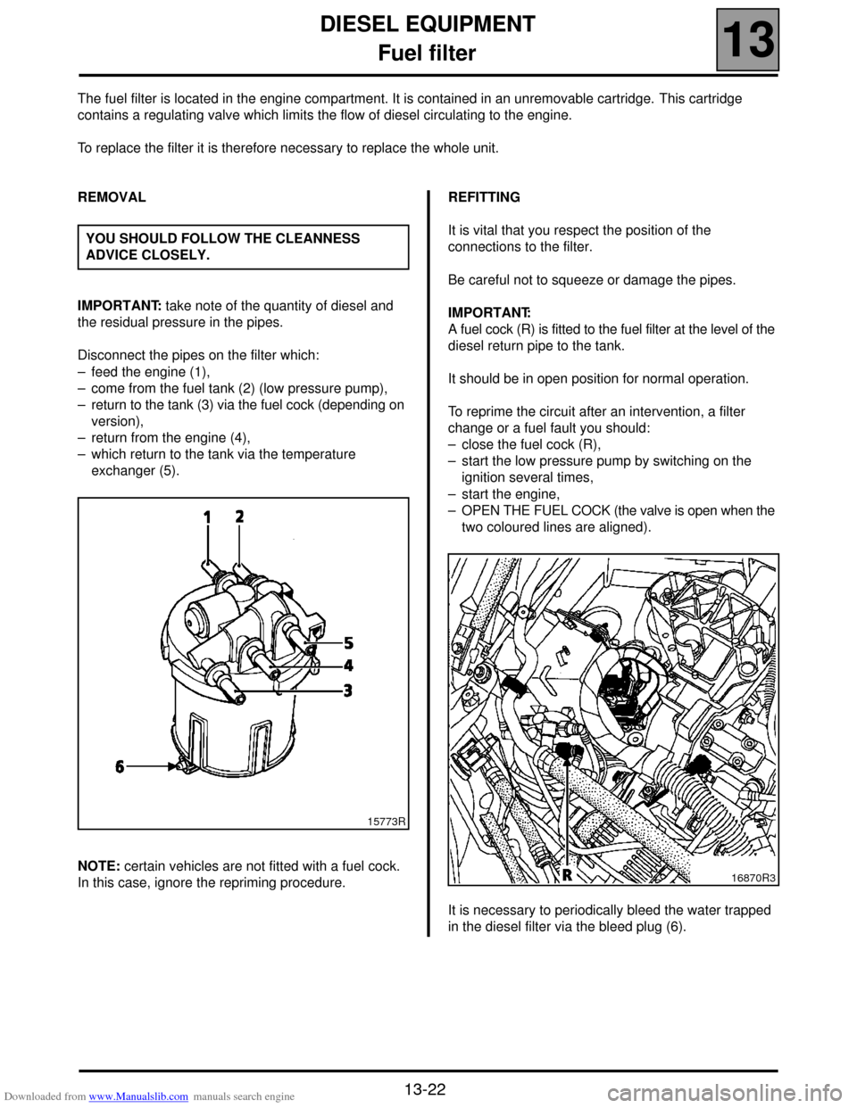
Disconnect the pipes on the filter which:
– feed the engine (1),
– come from the fuel tank (2) (low pressure pump),
– return to the tank (3) via the fuel cock (depending on
version),
– return from the engine (4),
– which return to the tank via the temperature
exchanger (5).
NOTE: certain vehicles are not fitted with a fuel cock.
In this case, ignore the repriming procedure.REFITTING
It is vital that you respect the position of the
connections to the filter.
Be careful not to squeeze or damage the pipes.
IMPORTANT:
A fuel cock (R) is fitted to the fuel filter at the level of the
diesel return pipe to the tank.
It should be in open position for normal operation.
To reprime the circuit after an intervention, a filter
change or a fuel fault you should:
– close the fuel cock (R),
– start the low pressure pump by switching on the
ignition several times,
– start the engine,
– OPEN THE FUEL COCK (the valve is open when the
two coloured lines are aligned).
It is necessary to periodically bleed the water trapped
in the diesel filter via the bleed plug (6). YOU SHOULD FOLLOW THE CLEANNESS
ADVICE CLOSELY.
15773R
16870R3
Page 90 of 118

Downloaded from www.Manualslib.com manuals search engine DIESEL EQUIPMENT
Pressure regulator
13
13-39
Pressure regulator
TIGHTENING TORQUES (In daN.m or/and °)
Regulator bolt 0.9 ± 0.1
IMPORTANT: before any intervention, connect
the after-sales diagnostic tool, query the injection
computer and check that the injection rail is not
under pressure. Take note of the fuel temperature.
PRESSURE REGULATOR (2)
REMOVAL
Disconnect the battery.
Remove the regulator connector.
Remove the retaining bracket for the diesel
temperature sensor.
Unscrew the regulator mounting bolts.
Remove the regulator by turning in an anticlockwise
direction (do not use any tools as a lever when
removing the pump regulator).REFITTING
Change the seals.
Dampen the seals with clean diesel.
Replace the regulator in the pump by turning it in an
anticlockwise direction (do not use any tools as a lever
when replacing the pump regulator).
Fit the mounting bolts then tighten to torque.
Connect the connector. YOU SHOULD FOLLOW THE CLEANNESS
INSTRUCTIONS CLOSELY.
After any intervention, check that there are no leaks in the diesel circuit.
Start the engine at idling speed until the fan starts up, then accelerate
several times under no load.