Page 11 of 52

Downloaded from www.Manualslib.com manuals search engine ENGINE AND PERIPHERALS
Engine and transmission assembly
10
10-7
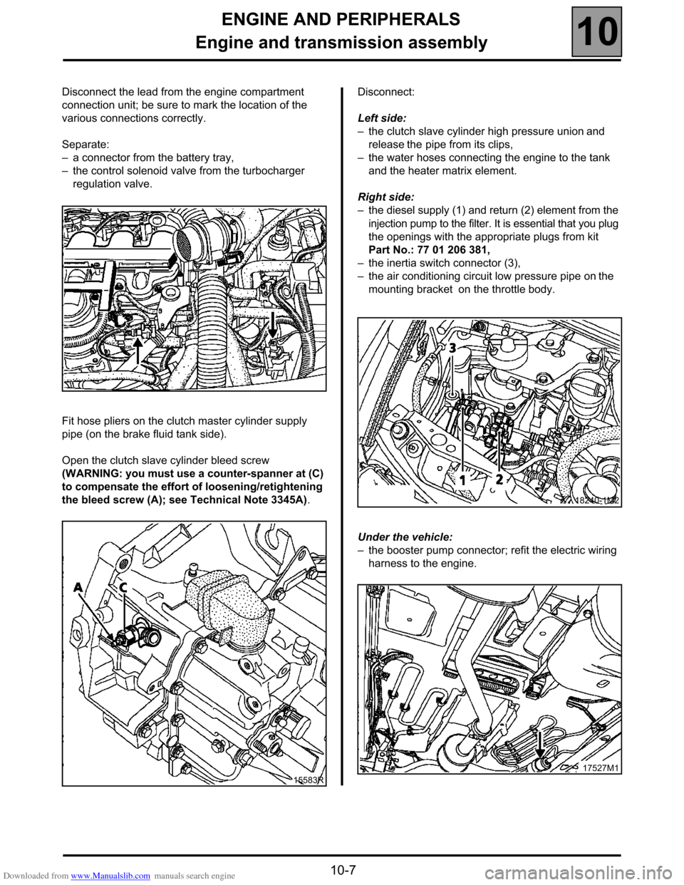
Disconnect the lead from the engine compartment
connection unit; be sure to mark the location of the
various connections correctly.
Separate:
–a connector from the battery tray,
–the control solenoid valve from the turbocharger
regulation valve.
Fit hose pliers on the clutch master cylinder supply
pipe (on the brake fluid tank side).
Open the clutch slave cylinder bleed screw
(WARNING: you must use a counter-spanner at (C)
to compensate the effort of loosening/retightening
the bleed screw (A); see Technical Note 3345A).Disconnect:
Left side:
–the clutch slave cylinder high pressure union and
release the pipe from its clips,
–the water hoses connecting the engine to the tank
and the heater matrix element.
Right side:
–the diesel supply (1) and return (2) element from the
injection pump to the filter. It is essential that you plug
the openings with the appropriate plugs from kit
Part No.: 77 01 206 381,
–the inertia switch connector (3),
–the air conditioning circuit low pressure pipe on the
mounting bracket on the throttle body.
Under the vehicle:
–the booster pump connector; refit the electric wiring
harness to the engine.
15583R
18240-1M2
17527M1
Page 13 of 52

Downloaded from www.Manualslib.com manuals search engine ENGINE AND PERIPHERALS
Engine and transmission assembly
10
10-9
REFITTING - Special points
Pre-position the gearbox control cables.
Position the engine/gearbox assembly in its
compartment. Check the rear of the gearbox in relation
to the sub-frame.
Fitting suspended mountings: see section 19
"Suspended mountings".
Tighten all the bolts, nuts and studs to the
recommended torques.
Refitting is the reverse of removal.
Press the brake pedal several times to bring the
pistons into contact with the brake pads.
Reprogram all the components deprogrammed by
disconnecting the battery.
Fill the refrigerant circuit using the filling station (see
section 62 "Air conditioning").
Refrigerant fluid R134a: 800 ± 20 g.
Carry out:
–filling and bleeding of the cooling circuit (see
section 19),
–filling and bleeding of the power assisted steering
circuit,–bleed the hydraulic clutch circuit.
Damage to the union leads to replacement of the
master cylinder, and thus removal/refitting of the
gearbox.IT IS ESSENTIAL THAT YOU FOLLOW THE
BLEEDING METHOD GIVEN BELOW
VERY IMPORTANT:
When bleeding use a 19 mm ring spanner to
immobilise the rotating union (C) while tightening
and loosening the bleed screw (A) so as not to
damage the slave cylinder and the union.
15583R
Page 14 of 52

Downloaded from www.Manualslib.com manuals search engine ENGINE AND PERIPHERALS
Engine and transmission assembly
10
10-10
BLEEDING METHOD TO BE USED:
(for two people).
1) Filling the circuit:
Check that the clutch pedal is in the top position; put
it in this position and hold it by hand if necessary.
Fill the hydraulic circuit by connecting a filling system
and applying pressure to the tank, open the bleed
screw (A) (always compensate for the force using a
counter-spanner) and allow a little fluid to escape
(approximately 0.5 l) through a transparent tube
connected to the bleed screw. Close the bleed
screw.
2) Final bleeding of the circuit:
One operator slowly disengages fully and keeps the
pedal depressed. Wait approximately ten seconds in
this situation. With the pedal still depressed, a
second operator opens the bleed screw briefly (A).
With the bleed screw closed again, the operator
inside the vehicle releases the clutch pedal and
slowly lifts it to top position by hand (It is normal that
the pedal does not return independently in this
configuration).
After a few seconds repeat the operations described
above in 2) as often as required until no more
bubbles escape when bleeding. Then repeat these
operations five times to ensure that the system has
been bled correctly.
These repeated bleedings allow the slave cylinder to
eject all the air trapped in any section between the
stop and the bleed screw and which has not been
"cleaned" by the flow of liquid when refilling using the
traditional pressurisation system.
An air bubble in the circuit, no matter how small, may
lead to operating faults such as: incorrect pedal
return, crashing of the gears,..., which may lead to
incorrect fault finding and unnecessary replacement
of a component in the clutch circuit.
Page 45 of 52
Downloaded from www.Manualslib.com manuals search engine MANUAL GEARBOX
Removal - refitting
21
21-4
Removal - refitting
The method for removing/refitting the PK1 G9T
gearbox is the same as for the G8T engine.
See Workshop Repair Manual 315 section 21
"Transmission: removing/refitting the PK1
gearbox".
Please observe the recommendations for bleeding the
hydraulic clutch system given in Technical Note
3345A when refitting.
IMPORTANT:
The TDC sensor (1) may be moved during the gearbox
removal/refitting operation.
If necessary, push this until it is in contact with the
backing plate.
Too great a gap could cause a starting fault which is
not visible on the fault finding tool.
16027M1