2000 MITSUBISHI MONTERO spark plug
[x] Cancel search: spark plugPage 398 of 1839

Page 399 of 1839

Page 400 of 1839

Page 749 of 1839

16-1
ENGINE
ELECTRICAL
CONTENTS
CHARGING SYSTEM 2................
GENERAL INFORMATION 2................
SERVICE SPECIFICATIONS 3..............
SPECIAL TOOL 4.........................
ON-VEHICLE SERVICE 5..................
Alternator Output Line Voltage Drop Test 5....
Output Current Test 6.......................
Regulated Voltage Test 8....................
Waveform Check Using An Analyzer 11.......
ALTERNATOR 13.........................
STARTING SYSTEM 23................
GENERAL INFORMATION 23..............
SERVICE SPECIFICATIONS 24............
STARTER MOTOR 24.....................
IGNITION SYSTEM 37.................
GENERAL INFORMATION 37..............
SERVICE SPECIFICATIONS 38............
SPECIAL TOOL 38.......................
ON-VEHICLE SERVICE 38................
Ignition Coil (With Built-in Power Transistor)
Check 38...................................
Spark Plug Check and Cleaning 39...........
Ignition Failure Sensor Check 40.............
Camshaft Position Sensor Check, Crank angle
Sensor Check, Detonation Sensor Check 40...
IGNITION COIL <6G7> 41.................
CRANKSHAFT ANGLE SENSOR
<6G7> 42................................
CAMSHAFT POSITION SENSOR
<6G7> 42................................
DETONATION SENSOR <6G7> 43.........
GLOW SYSTEM 44....................
GENERAL INFORMATION 44..............
SERVICE SPECIFICATIONS 45............
ON-VEHICLE SERVICE 45................
Self-regulating Glow System Check 45........
Glow & EGR Control Unit Check 48..........
Engine ECU Check 49.......................
Glow Plug Relay Check 50..................
Glow Plug Check 51........................
Engine Coolant Temperature Sensor
Check 51...................................
GLOW PLUG 52..........................
www.WorkshopManuals.co.uk
Purchased from www.WorkshopManuals.co.uk
Page 787 of 1839

ENGINE ELECTRICAL -Ignition System16-39
Voltage: 1.5VTerminal No.
123
When current is
flowing
When current is
not flowing
SECONDARY COIL CHECK
NOTE
It is impossible to check the secondary coil through the
continuity check as a diode is integrated in the secondary
coil circuit of this ignition coil. So, check the secondary coil
in the following procedure.
1. Disconnect the ignition coil connector.
2. Remove the ignition coil and install a new spark plug
to the ignition coil.
3. Connect the ignition coil connector.
4. Earth the side electrode of the spark plug and crank
the engine.
5. Check that spark is produced between the electrodes of
the spark plug.
6. If no spark is produced, replace the ignition coil with a
new one and recheck.
7. If spark is produced with the new ignition coil, replace
the old one as it is faulty. If no spark is produced again,
the ignition circuit is suspected as faulty. Check the ignition
circuit.
SPARK PLUG CHECK AND CLEANING
Caution
1. The spark plug gap for iridium plugs should not be
adjusted.
2. Cleaning iridium plugs may result in damage to the
iridium tip. Therefore, if cleaning is necessary
because the plug is sooty, use a plug cleaner, and
do not clean the plug for more than 20 seconds in
order to preserve the electrodes. A wire brush should
never be used.
3. The spark plugs in GDI engines are special iridium
plugs in which the electrodes can become black even
when the plugs are working normally. Carbon which
may become deposited on these plugs burns off more
readily than with conventional plugs, and so should
not cause any problems with spark plug performance.
Judgement of whether a spark plug is operating
normally or not should be made by checking the
insulation resistance.
www.WorkshopManuals.co.uk
Purchased from www.WorkshopManuals.co.uk
Page 1575 of 1839

CHASSIS ELECTRICAL-Battery54A-5
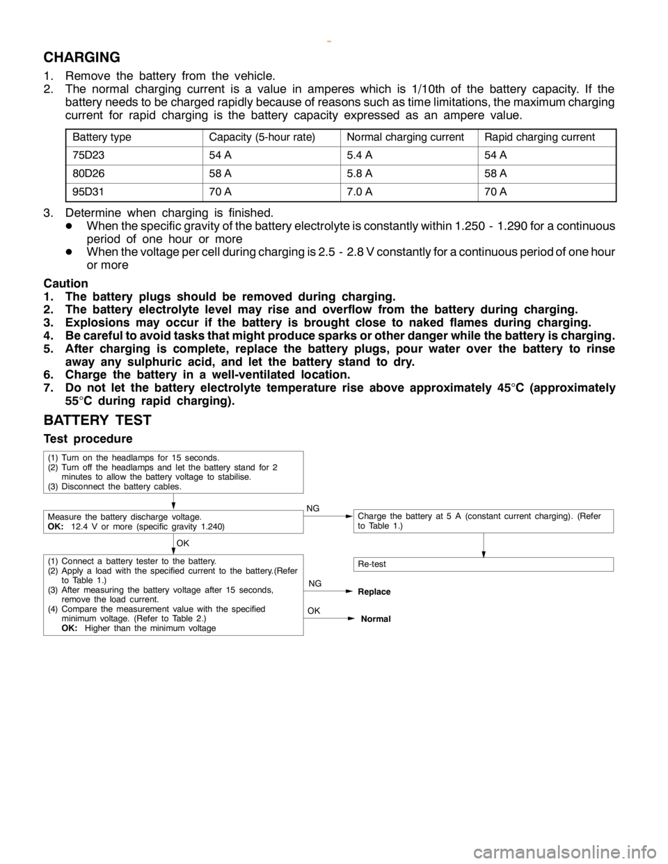
CHARGING
1. Remove the battery from the vehicle.
2. The normal charging current is a value in amperes which is 1/10th of the battery capacity. If the
battery needs to be charged rapidly because of reasons such as time limitations, the maximum charging
current for rapid charging is the battery capacity expressed as an ampere value.
Battery typeCapacity (5-hour rate)Normal charging currentRapid charging current
75D2354 A5.4 A54 A
80D2658 A5.8 A58 A
95D3170 A7.0 A70 A
3. Determine when charging is finished.
DWhen the specific gravity of the battery electrolyte is constantly within 1.250 - 1.290 for a continuous
period of one hour or more
DWhen the voltage per cell during charging is 2.5 - 2.8 V constantly for a continuous period of one hour
or more
Caution
1. The battery plugs should be removed during charging.
2. The battery electrolyte level may rise and overflow from the battery during charging.
3. Explosions may occur if the battery is brought close to naked flames during charging.
4. Be careful to avoid tasks that might produce sparks or other danger while the battery is charging.
5. After charging is complete, replace the battery plugs, pour water over the battery to rinse
away any sulphuric acid, and let the battery stand to dry.
6. Charge the battery in a well-ventilated location.
7. Do not let the battery electrolyte temperature rise above approximately 45
°C (approximately
55
°C during rapid charging).
BATTERY TEST
Test procedure
OK
NG
Replace
Re-test
OK
Normal
(1) Connect a battery tester to the battery.
(2) Apply aloadwith the specified current to the battery.(Refer
to Table 1.)
(3) After measuring the battery voltage after 15 seconds,
remove the loadcurrent.
(4) Compare the measurement value with the specified
minimum voltage.(Refer to Table 2.)
OK:Higher than the minimum voltage
Measure the battery discharge voltage.
OK:12.4 V or more (specific gravity 1.240)NGCharge the battery at 5 A (constant current charging). (Refer
to Table 1.)
(1) Turn on the headlamps for 15 seconds.
(2) Turn off the headlamps and let the battery stand for 2
minutes to allow the battery voltage to stabilise.
(3) Disconnect the battery cables.
www.WorkshopManuals.co.uk
Purchased from www.WorkshopManuals.co.uk