Page 166 of 280
 to search for a par-
ticular track, etc. When this button is
pressed, the first 10 seconds of each track
on the disc will")
FOR PLEASANT DRIVING
6–26
How to use the SCAN button
Use the SCAN button (9) to search for a par-
ticular track, etc. When this button is
pressed, the first 10 seconds of each track
on the disc will be played.
The disc will advance at fast-forward speed
between each 10-second played in this way.
Press the SCAN button again, to play the
track ordinary. After completion of this scan-
ning of tracks, the disc will begin ordinary
play.
To change the order of tracks
played back (For CD player)
Press the RDM button (11), and the RDM
indicator (16) will illuminate and will be ran-
domly selected, tracks for playback. To re-
lease, press the button again.
To change the order of discs
played back (For CD autochanger)
Press the RDM button (11), and the RDM
indicator (16) will illuminate and tracks for
playback will be selected randomly from all
discs loaded into the changer.
To r e lease, press the button again.
H11F032a
Audio system anti-theft
feature
EH11F-Ed
To prevent theft of the audio system, the con-
trol panel can be removed. Always remove
the control panel when you leave the ve-
hicle.
Removing the control panel
Turn the ignition switch to the OFF position.
Then slide the release button (A) to the left
and remove the control panel from the audio
system. (When sliding the release button,
place one hand on the control panel to pre-
vent it from falling out.) The lamp (B) will start
flashing.
H11F033a
Refitting the control panel
Insert the control panel into the latches at the
right-hand side of the cutout on the audio
system. Then, press the left-hand side of the
control panel into the cutout until it locks in
position. The lamp (B) will stop flashing.
Next, turn the ignition switch to the ON posi-
tion.
NOTE
(1) Do not leave the control panel in any
place where it may become hot (for
example, the dashboard) or in any
place where it may become wet.
(2) If you lose the control panel, contact an
authorized MITSUBISHI dealer.
Page 185 of 280

FOR PLEASANT DRIVING
6–45
G13A018a
Vanity mirrorEG13A - A
A vanity mirror is fitted to the rear of the sun
visor on the passenger side.
G31A082a
Cigarette lighterEG31A-Al
The cigarette lighter can be used while the
ignition switch is in either “ON” or “ACC”.
1-Push all the way in.
The lighter will automatically return to its orig-
inal position with a “click” when ready.
Pull it out for use.
After use, insert the lighter to its original posi-
tion in the socket.
NOTE
Do not leave the cigarette lighter removed
from its socket, because the socket might
become clogged by foreign material and be
short - circuited.
CAUTION
(1) Do not touch heating element or
lighter housing, hold the knob
only as burns may occur.
(2) Do not allow children to operate
or play with the cigarette lighter
as burns may occur.
(3) Something is wrong with the ciga-
rette lighter if it does not pop back
out within approximately 30 sec-
onds of being pushed in.
Leaving the cigarette lighter
pushed in for an extended period
could cause fire. If it does not pop
out by itself, pull it out and have
the problem corrected at an auth-
orized MITSUBISHI dealer.
(4) Do not leave the cigarette lighter
pushed in or insert the cigarette
lighter from another vehicle.
Otherwise, the lighter may over-
heat and cause fire.
(5) It is recommended that only the
lighter be inserted in its socket.
Use of “plug - in” type accessories
may damage the socket and result
in poor retention of the lighter.
Page 204 of 280
.
2-To store
Turn the shaft end by hand to expand
the ja")
FOR EMERGENCIES
8–4
N21C026a
JackEN21C - Ba
1-To remove
Turn the shaft end so that the jack re-
tracts and detach it from fixing bracket
(A).
2-To store
Turn the shaft end by hand to expand
the jack until it is secured firmly in posi-
tion.
Jacking up the vehicleEN22ALEb
1. Park the vehicle on a level and stable
ground.
2. Activate the hazard flashers and turn
the ignition key to the “LOCK” position.
3. Set the parking brake firmly, move the
gearshift lever (manual transmission)
to the 1st position or move the selector
lever (automatic transmission) to the
“P” (PARK) position.
N22A220a
4. Apply a chock or block (A) at the tyre
diagonally opposite the tyre (B) to be
changed.
CAUTION
Be sure to apply a chock to the rel-
evant tyre when jacking up the ve-
hicle. If the vehicle moves while
jacked up, the jack could slip out of
position, leading to an accident.
NOTE
(1)The chock shown in the illustration is
not supplied with the vehicle. It is rec-
ommended one be obtained and car-
ried for use if required.
(2) If a chock is not available, use a stone
or any other object that is large enough
to hold the wheel in position.
Page 213 of 280

FOR EMERGENCIES
8–13
Front
N25A200a
Towing with a rope
1. For vehicles with automatic transmis-
sion check the automatic transmis-
sion fluid level. (Refer to “Automatic
transmission fluid” on page 9–4.)
If the fluid level is low, transport the ve-
hicle with all wheels off the ground.
CAUTION
If the vehicle is out of automatic trans-
mission fluid, the transmission could
be damaged.
2. The towing hooks (A) are located as
shown in the illustrations. Attach the
tow rope to the towing hooks.
Rear
N25A057a
NOTE
(1) Using any part other than the desig-
nated towing hooks (A) could result in
damage to vehicle body.
(2) Use care that the towing rope is kept as
horizontal as possible.
An angled towing rope can damage the
vehicle body.
(3) Never attempt to tow out a ditched ve-
hicle because the towing rope cannot
be kept horizontal.
3. Turn the ignition switch to the “ACC” or
“ON” position to unlock the steering
wheel.
CAUTION
(1) As the engine is not running, the
brake booster and power steer-
ing pump do not operate. This
means higher brake depression
force and higher steering effort
are required. Therefore vehicle
operation is more difficult than
usual.
(2) Do not leave the key in the
“LOCK” position. If the key is re-
moved while driving, the steering
will be locked causing loss of
control.
4. Turn on the hazard warning lamps.
5. Move the gearshift lever (manual
transmission) or the selector lever (au-
tomatic transmission) to Neutral or the
“N” position.
6. During towing make sure that close
contact is maintained between the
drivers of both vehicles, and that the
vehicles travel at low speed. Avoid
abrupt starting or stopping which
might subject the vehicles to shock.
Page 215 of 280
 This vehicle cannot be towed by
a tow truck using Type A equip-
ment to prevent the bumper from
deformation. If this vehicle is
tow")
FOR EMERGENCIES
8–15
Towing the vehicle by a tow truck
CAUTION
(1) This vehicle cannot be towed by
a tow truck using Type A equip-
ment to prevent the bumper from
deformation. If this vehicle is
towed, use Type B, Type C, Type
D or Type E equipment.
(2) In case the vehicle with automatic
transmission must be towed far-
ther than 30 km, transport the ve-
hicle with all wheels off the
ground (Type B or C) or with front
wheels off the ground (Type D).
(3) If the transmission is not operat-
ing, transport the vehicle with all
wheels off the ground (Type B or
C).
Towing with front wheels off the
ground (Type D)
Release the parking brake. Place the gear-
shift lever (manual transmission) or the se-
lector lever (automatic transmission) in the
“N” (NEUTRAL) position.
Towing with rear wheels off the
ground (Type E)
Place the gearshift lever (manual trans-
mission) or the selector lever (automatic
transmission) in the “N” (NEUTRAL) posi-
tion.
Turn the ignition key to the “ACC” position
and secure the steering wheel in a straight-
ahead position with a rope, etc.
Never place the ignition key in the “LOCK”
position. It is dangerous as the steering
wheel may lock.
Engine overheatingEN26A - Ub
If the water temperature gauge indication re-
mains in the overheating zone for a long
time, the engine may be overheating. If this
occurs, take the following corrective
measures :
1. Stop the vehicle in a safe place.
Page 218 of 280

FOR EMERGENCIES
8–18
CAUTION
Check the other vehicle. It must have
a 12-volt battery.
If the other system isn’t 12-volt, short-
ing can damage both vehicles.
2. You could be injured if the vehicles roll.
Set the parking brake firmly on each
vehicle. Put an automatic trans-
mission in “P” (PARK) or a manual
transmission in “N” (Neutral). Turn off
the ignition switch.
WARNING
Tu r n o f f t h e ignition on both vehicles
beforehand. Use care to make sure
that the cables or your clothes do not
get caught by the fan or drive belt.
Personal injury could result.
NOTE
Turn off all lamps, heater and other electrical
loads. This will avoid sparks and help save
both batteries.
3. Make sure battery electrolyte is at the
proper level.
Refer to “Battery” on page 9–7.
WARNING
If electrolyte fluid is not visible, or ap-
pears to be frozen, do not attempt
jump starting!
A battery might rupture or explode if
the temperature is below the freezing
point or if it is not filled to the proper
level.
Petrol-powered vehicles (1300 models)
N28A195a
4. Connect one end of one jumper cable
to the positive (+) terminal of the dis-
charged battery, and the other end to
the positive (+) terminal of the booster
battery.
5. Connect one end of the other jumper
cable to the negative (-) terminal of the
booster battery, and the other end to
the engine block of the vehicle with the
discharged battery at the point farthest
from the battery.
NOTE
Remove the cover before connecting the
jumper cable to the positive terminal of the
battery.
Page 224 of 280
FOR EMERGENCIES
8–24
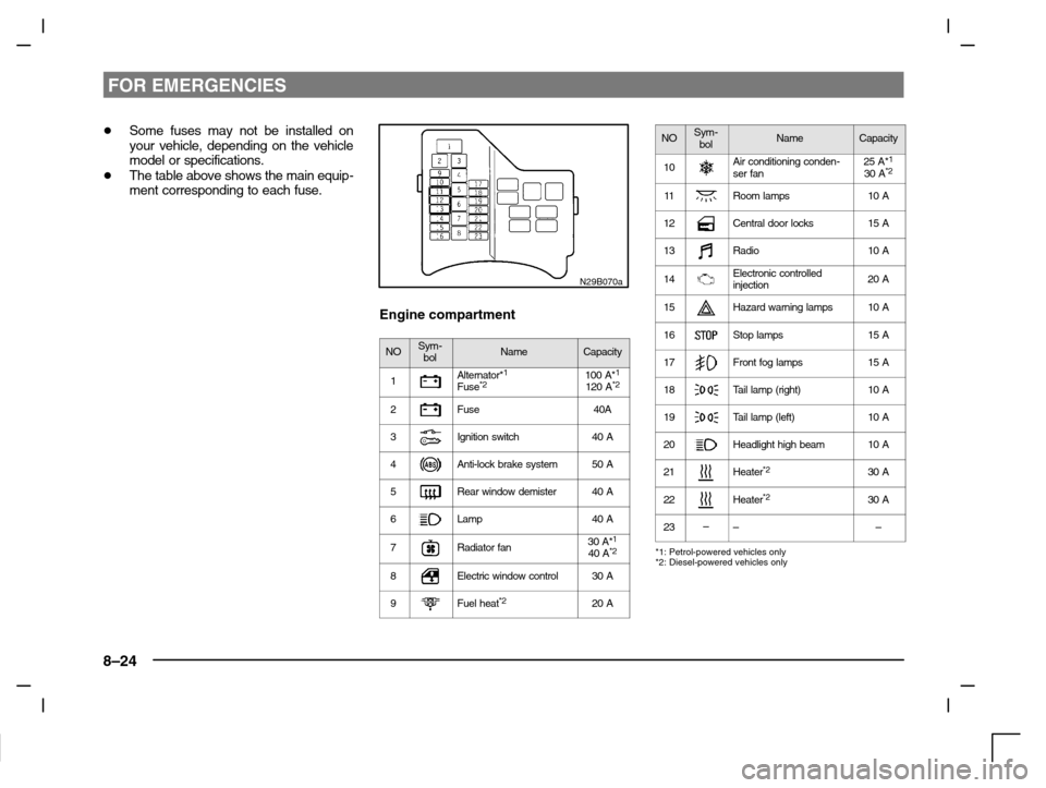
�Some fuses may not be installed on
your vehicle, depending on the vehicle
model or specifications.
�The table above shows the main equip-
ment corresponding to each fuse.
N29B070a
Engine compartment
NOSym-
bolNameCapacity
1Alternator*1Fuse*2100 A*1120 A*2
2Fuse40A
3Ignition switch40 A
4Anti-lock brake system50 A
5Rear window demister40 A
6Lamp40 A
7Radiator fan30 A*140 A*2
8Electric window control30 A
9Fuel heat*220 A
NOSym-
bolNameCapacity
10Air conditioning conden-
ser fan25 A*130 A*2
11Room lamps10 A
12Central door locks15 A
13Radio10 A
14Electronic controlled
injection20 A
15Hazard warning lamps10 A
16Stop lamps15 A
17Front fog lamps15 A
18Ta i l l a m p (right)10 A
19Ta i l l a m p (left)10 A
20Headlight high beam10 A
21–Heater*230 A
22–Heater*230 A
23–––
*1: Petrol-powered vehicles only
*2: Diesel-powered vehicles only
Page 225 of 280
FOR EMERGENCIES
8–25
�Some fuses may not be installed on
your vehicle, depending on the vehicle
model or specifications.
�The table above shows the main equip-
ment corresponding to each fuse.
N29C013a
Changing a fuseEN29C - Ce
1. Before replacing a fuse, always turn
off the electrical circuit concerned and
turn the ignition key to the “LOCK”
position.
2. Remove the fuse box cover.
3. Referring to the fuse load capacity
table, check the fuse pertaining to the
problem.
A - Fuse is OK
B - Blown fuse
N29C008a
4. There is a fuse removing tool in the
fuse cover of the passenger com-
partement. First take the fuse remov-
ing tool out of the fuse cover slowly
and then by using the fuse removing
tool, pull the fuse straight out from the
fuse box. If it is not blown, something
else must be causing the problem;
contact an authorized MITSUBISHI
dealer to have the problem checked.