Page 97 of 130

Open hood.
Move retaining clamps (4) aside and remove cover (3). Pull off electrical connector (10). Unhook clamping ring
and pull out bulb together with clampin")
Bulb for High Beam H1 (55 W)
Open hood.
Move retaining clamps (4) aside and remove cover (3). Pull off electrical connector (10). Unhook clamping ring
and pull out bulb together with clamping ring. Remove bulb. Insert new bulb (seating properly in cutouts of bulb
socket), mount clamping ring. Reinstall and push electrical connector on securely. Reinstall cover and fasten
with retaining clamp (4).
Turn Signal, Parking, Side Marker and Standing Lamp
(2357 NA [28.5/8.3 W/30/2.2 cp bulb])
Open hood.
Squeeze latch (1) together and lift complete lamp assembly out to front of vehicle. Twist bulb socket (2)
counterclockwise and pull out. Push bulb into socket, turn counterclockwise and remove. Insert new bulb in socket
push in and twist clockwise. Reinstall bulb socket. Reinstall lamp assembly by sliding tabs (3) into guides (4) until
properly seated.
1. Latch for turn signal, parking, side marker, and standing lamp assembly
2. Bulb socket for turn signal, parking, side marker, and standing lamp
3. Tab
4.Guide
Page 98 of 130

Correct headlamp adjustment is
extremely important. To check and
readjust a headlamp follow steps 1
through 7. Please note:
• Horizontal")
Adjusting Headlamp Aim (Halogen)
Correct headlamp adjustment is
extremely important. To check and
readjust a headlamp follow steps 1
through 7. Please note:
• Horizontal aim will change and
must be corrected as described
below, whenever a vertical
adjustment is made.
• Low beam adjustments
simultaneously aim the high
beam and fog lamp.
• Vehicle should have a normal
trunk load.
1. Park vehicle on level surface approximately 25 ft. (7.6 m)
from a vertical test screen or wall. The centerline of the
vehicle must be at a 90° angle to the test screen.
2. (low beams on):
Using a carpenter's level, align and mark a vertical centerline
(8) on the test screen using the vertex of the angle formed in
each beam image. As a check, the distance between centerlines
should be 47 1/4 inches (1198 mm). If the distance does not check,
have the system verified at an authorized Mercedes-Benz dealer.
3. Open hood, depress latch (1), and remove access cover (2) from
the headlamp.
4. Vertical headlamp aim
(low beams on): Turn adjusting screw (3) (counterclockwise to adjust
headlamp downward, clockwise upward) until bubble in the level (4) is
centered on the "0" mark.
Graduations: 0.18° pitch.
5. Horizontal headlamp aim (low beams on):
Turn adjusting screw (5) (Right front headlamp: counterclockwise
to adjust to the left, clockwise to the right; left front head-
lamp: counterclockwise to adjust to the right, clockwise to the
left.) until the headlamps (low beam) illuminate the test screen
as shown. The vertex of the angle formed in each beam
image should align with the vertical centerline (8) of each lamp.
The left and right headlamps must be adjusted individually.
6. The indicator (6) in the sight glass should align with the
"0" mark after any horizontal adjustment. If it does not, slide
the "0" mark on the scale (7) until it aligns with the indicator (6).
Graduations: 0.38° pitch.
7. Reinstall access cover(2).
Note:
If it is not possible to obtain a proper headlamp adjustment, have
the system checked at your authorized Mercedes-Benz dealer.
Page 99 of 130

Correct headlamp adjustment is
extremely important. To check and
readjust a headlamp, follow steps 1
through 5. Please note:
• Low beam adjustments")
Adjusting Headlamp Aim
(Xenon)
Correct headlamp adjustment is
extremely important. To check and
readjust a headlamp, follow steps 1
through 5. Please note:
• Low beam adjustments
simultaneously aim the high
beam and fog lamp.
• Vehicle should have a normal
trunk load.
• Vertical aim adjustments
change horizontal aim.
1. Park vehicle on level surface approximately 25 ft. (7.6 m) from a vertical
test screen or wall. The centerline of the vehicle must be at a 90° angle
to the test screen.
2. (Low beams on):
Using a carpenter's level, align and mark a vertical centerline
(8) on the test screen using the vertex of the angle formed in
each beam image. As a check, the distance between center-
lines should be 47 1/4 inches (1198 mm). If the distance does not check,
have the system verified at an authorized Mercedes-Benz dealer.
3. (Low beams off):
Measure the vertical height from the floor to reference point (10)
on low beam lens. Subtract approx. 2 inches (53 mm) from
measurement, and mark a horizontal centerline (9) on the
test screen at the resulting height from the floor. It must be
at a 90° angle to the vertical centerline.
4. Open hood.
5. Vertical headlamp aim (low beams on):
Simultaneously turn adjusting screws (1 and 2) equally in the
same direction (counterclockwise to adjust headlamp downward,
clockwise upward) until the headlamp (low beam)
illuminates the test screen as shown.
The left and right headlamps must be adjusted individually.
Note:
If it is not possible to obtain a proper headlamp adjustment, have
the system checked at your authorized Mercedes-Benz dealer.
Page 100 of 130
Taillamp Assemblies
1. Stop lamp
(21 W/32 cp bulb)
2. Turn signal lamp
(21 W/32 cp bulb)
3. Backup lamp
(21 W/32 cp bulb)
4. Tail, parking, side marker and standing lamp
(5 W/4 cp bulb)
5. Passenger side:
Tail and parking lamp
(21/4W bulb) Driver's side:
Tail, parking and rear fog lamp
(21/4 bulb)
To replace bulbs:
From inside trunk, open locks and swing open lamp cover.
Turn locking lever on lamp to horizontal position and remove bulb carrier.
Push down on bulb to be changed, twist counterclockwise and remove.
Page 101 of 130

Battery
Warning !
Failure to follow these instructions can result in severe injury or death. Never lean over batteries while
connecting, you might get injured. Battery fluid contains sulfuric acid. Do not allow this fluid to come in
contact with eyes, skin or clothing. In case it does, immediately flush affected area with water and seek
medical help if necessary. A battery will also produ ce hydrogen gas, which is flammable and explosive.
Keep flames or sparks away from battery, avoid im proper connection of jumper cables, smoking etc..
Important !
Battery maintenance information:
The battery is located in the trunk under the trunk floor. The fluid level must be checked at every A and B service.
Always insure that the fluid level is at the specified maximum level and that only distilled water is used. Failure to
maintain proper fluid level may result in cell deterioration and possible battery rupture. The service life of the battery is
dependent on its condition of charge. The battery should alwa ys be kept sufficiently charged, in order to last an
optimum length of time.
Therefore, we strongly recommend that you have the battery charge checked frequently, and corrected if
necessary, especially if you use the vehicle less than approximately 200 miles (300 km) per month, mostly for
short distance trips, or if it is not used for long periods of time.
Only charge a battery with a battery charger after the battery has been disconnected from the vehicle electrical circuit.
Always disconnect the battery negative lead first and connect last. When removing and connecting the battery,
always make sure that all electrical consumers are off and the electronic key is in steering lock position 0. The battery
and its vent tube must always be securely installed when the car is in operation. While the engine is running the
battery terminal clamps must not be loosened or detached, otherwise the generator and other electronic components
would be damaged.
Note:
After reconnecting the battery also resynchronize the Express feature of the power windows, the
sliding/pop-up roof, and the Electronic Stability Program (ESP) (see Power seats, front, Head
restraints, Power windows, Sliding/pop-up roof, and Electronic stability program in Index).
Battery Recycling
Batteries contain materials that can harm the environment with improper disposal. Large 12 Volt storage batteries
contain lead. Recycling of batteries is the preferred method of disposal. Many states require sellers of batteries to
accept old batteries for recycling.
Page 102 of 130
Fuses
1. Main fuse box in engine compartment
2. Auxiliary fuse box in trunk
3. Auxiliary fuse in trunk
4. Auxiliary fuse in engine compartment
Before replacing a blown fuse, determine the cause of the short circuit. Spare fuses are supplied inside the main fuse
box. Observe amperage and color of fuse. To gain access to the main fuse box (1), press clamp (arrow) , lift the fuse
box cover up and remove it. A special fuse puller comes with the vehicle tools. Always use a new fuse for
replacement. Never attempt to repair or bridge a blown fuse. After replacing a blown fuse, close fuse box cover. To
close the main fuse box, engage cover at the rear and secure with clamp.
Page 103 of 130

Jump Starting
Warning !
Failure to follow these directions will cause damage to the electronic components, and can
lead to a battery explosion and severe injury or death. Never lean over batteries while
connecting or jump starting, you might get injure d. Battery fluid contains sulfuric acid. Do
not allow this fluid to come in contact with ey es, skin or clothing. In case it does, immediately
flush affected area with water, and seek medical help if necessary. A battery will also produce
hydrogen gas, which is flammable and very explosive. Keep flames or sparks away from
battery, avoid improper connection of jumper cables, smoking etc.. Read all instructions
before proceeding.
If the battery is discharged, the engine should be start ed with jumper cables and the (12 V) battery of
another vehicle.
The battery is located in the trunk under the trunk floor.
Proceed as follows:
1 . Position the vehicle with the charged battery so that the jumper cables will reach, but never
let the vehicles touch. Make sure the jump er cables do not have loose or missing insulation.
2. On both vehicles:
• Turn off engine and all lights and accessories, except hazard warning flashers or work lights.
• Apply parking brake and shift selector lever to position "P".
Important !
3. Clamp one end of the first jumper cable to the positive (+) terminal of the discharged
battery and the other end to the positive (+ ) terminal of the charged battery. Make sure
the cable clamps do not touch any other metal parts.
4. Clamp one end of the second jumper cable to the grounded negative (-) terminal of the
charged battery and the final connection to the negative (-) terminal of the discharged battery.
Important !
5. Start engine of the vehicle with the charged battery and run at high idle. Make sure the
cables are not on or near pulleys, fans, or other parts that will move when the engine is
started. Allow the discharged battery to charge for a few minutes. Start engine of the
disabled vehicle in the usual manner.
6. After the engine has started, remove jumper cables exactly reversing the above
installation sequence, starting with the last connection made first. When removing each
clamp, make sure that it does not touch any other metal while the other end is still attached.
Important !
A discharged battery can freeze at approx. +14°F (-10°C ). In that case, it must be thawed out before
jumper cables are used. A frozen battery can explode and cause personal injury.
Jumper cable specifications:
• Minimum cable cross-section of 25 mm
2 or approx. 2 AWG
• Maximum length of 11.5 ft. (3.5 m).
Note:
If engine does not run after several unsuccessful starting attempts, have it checked at the nearest
authorized Mercedes-Benz dealer. Excessive unbur ned fuel may damage the catalytic converter.
Page 104 of 130

Towing the Vehicle
Warning!
Prior to towing the vehicle with all wheels on the ground, make
certain that the electronic key is in steering lock position 2.
If the electronic key is left in the steering lock position 0 for
an extended period of time, it can no longer be turned in the
lock. In this case, the steering is locked. To unlock, remove
electronic key from steering lock and reinsert.
Important !
When towing the vehicle, please, note the following:
With the automatic central locking activated and the electronic key inn steering lock position 2, the vehicle
doors lock if the left front wheel as well as the right rear wheel are turning at vehicle speeds of approx. 9 mph (15
km/h) or more. To prevent the vehicle door locks from locking, deactivate the automatic central locking.
All except C 43 AMG
The rear towing eye is located at the right, below the bumper. The front towing eye is located on the passenger side
behind a cover in the bumper panel.
Models C 230 Kompressor and C 280:
Cover removal:
Insert finger in recess on left end of cover and pull cover out.
Cover installation:
Engage cover at top right and press cover in securely.
C 43 AMG
Model C 43 AMG
Cover removal:
Hold left and right end of cover and pull out.
Cover installation:
Engage cover at bottom and press in top securely.
We recommend that the vehicle be transported using flat bed equipment. This method is preferable to other types of
towing. The vehicle may be towed with all wheels on the ground and the selector lever in position "N" for distances up
to 30 miles (50 km) and at a speed not to exceed 30 mph (50 km/h). The electronic key must be in steering lock
position 2. To positively avoid a possibility of damage to the transmission, however, we recommend to disconnect the
drive shaft at the rear axle drive flange on any towing beyond a short tow to a nearby garage. Do not tow with sling-
type equipment. Towing with sling-type equipment over bumpy roads will damage radiator and supports. Use wheel
lift, dolly, or flat bed equipment, with electronic key in steering lock turned to position 0.
Warning !
With the engine not running, there Is no power assistance for the braking and steering systems.
In this case, it is important to keep in mind that a considerably higher degree of effort is necessary
to brake and steer the vehicle.
Note:
To signal turns while being towed with hazard warning flasher in use, turn electronic key in steering lock
to position 2 and activate combination switch for left or right turn signal in usual manner - only the
selected turn signal will operate. Upon cancelling the turn signal, the hazard warning flasher will operate again.
 1
1 2
2 3
3 4
4 5
5 6
6 7
7 8
8 9
9 10
10 11
11 12
12 13
13 14
14 15
15 16
16 17
17 18
18 19
19 20
20 21
21 22
22 23
23 24
24 25
25 26
26 27
27 28
28 29
29 30
30 31
31 32
32 33
33 34
34 35
35 36
36 37
37 38
38 39
39 40
40 41
41 42
42 43
43 44
44 45
45 46
46 47
47 48
48 49
49 50
50 51
51 52
52 53
53 54
54 55
55 56
56 57
57 58
58 59
59 60
60 61
61 62
62 63
63 64
64 65
65 66
66 67
67 68
68 69
69 70
70 71
71 72
72 73
73 74
74 75
75 76
76 77
77 78
78 79
79 80
80 81
81 82
82 83
83 84
84 85
85 86
86 87
87 88
88 89
89 90
90 91
91 92
92 93
93 94
94 95
95 96
96 97
97 98
98 99
99 100
100 101
101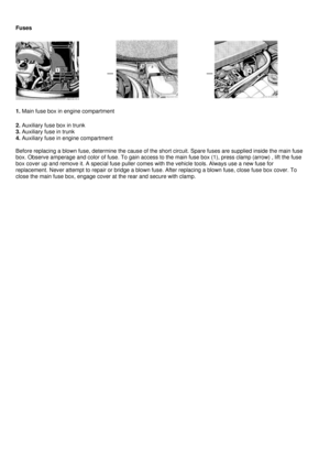 102
102 103
103 104
104 105
105 106
106 107
107 108
108 109
109 110
110 111
111 112
112 113
113 114
114 115
115 116
116 117
117 118
118 119
119 120
120 121
121 122
122 123
123 124
124 125
125 126
126 127
127 128
128 129
129
2. Turn signal lamp
(21 W/32 cp bulb)
3. Backup lamp
(21 W/32 cp bulb)
4. Tail, parking, side marker and standing")
