Page 1053 of 1111

5. ADJUST CAMBER
HINT:
�After adjusting the camber, inspect the caster and toe±i")
F02400
SA1204
± SUSPENSION AND AXLEFRONT WHEEL ALIGNMENT
SA±5
2005 Author�: Date�:
2000 LEXUS GS300/GS400 (RM718U)
5. ADJUST CAMBER
HINT:
�After adjusting the camber, inspect the caster and toe±in.
�Try adjusting the camber to the center value of the specifi-
cation.
(a) Loosen the camber adjusting cam nut of the lower sus-
pension arm.
(b) Turn the camber adjusting cam of the lower suspension
arm and adjust camber.
HINT:
Camber changes about 5' (0.08°) with each graduation of the
adjusting cam.
(c) Torque the camber adjusting cam nut of lower suspension
arm.
Torque: 172 N´m (1,755 kgf´cm, 127 ft´lbf)
6. ADJUST TOE±IN
(a) Remove the boot clips.
(b) Loosen the tie rod end lock nuts.
(c) Turn the left and right rack ends an equal amount to adjust
the toe±in.
HINT:
�Try to adjust the toe±in to the center value.
�Make sure that the lengths of the left and right rack ends
are same.
Rack end length difference: 1.5 mm (0.059 in.) or less
(d) Torque the tie rod end lock nuts.
Torque: 56 N´m (570 kgf´cm, 41 ft´lbf)
(e) Place the boot on the seat and clamp it.
HINT:
Make sure that the boots are not twisted.
Page 1058 of 1111
SA0RY±01
F03420
Washer
Suspension Member BraceBrake Caliper
Axle Carrier Assembly
Parking Brake
Cable
Parking Brake
Backing Plate Dust Deflector
Axle CarrierHub Bolt
Axle Hub
Snap Ring Disc
Lock Cap
289 (2,950, 213)
59 (600, 44)
75 (765, 55)
108 (1,100, 80)
104 (1,065, 77)Drive Shaft X6
� Cotter Pin
� Bearing
N´m (kgf´cm, ft´lbf): Specified torque
� Non±reusable part
50 (510, 37)
83 (850, 61)
110 (1,120, 81)
7.8 (80, 69 in.´lbf)
7.8 (80, 69 in.´lbf)
59 (600, 43)
ABS Speed Sensor
± SUSPENSION AND AXLEREAR AXLE CARRIER
SA±43
2043 Author�: Date�:
2000 LEXUS GS300/GS400 (RM718U)
REAR AXLE CARRIER
COMPONENTS
Page 1064 of 1111
SA0S4±01
F03421
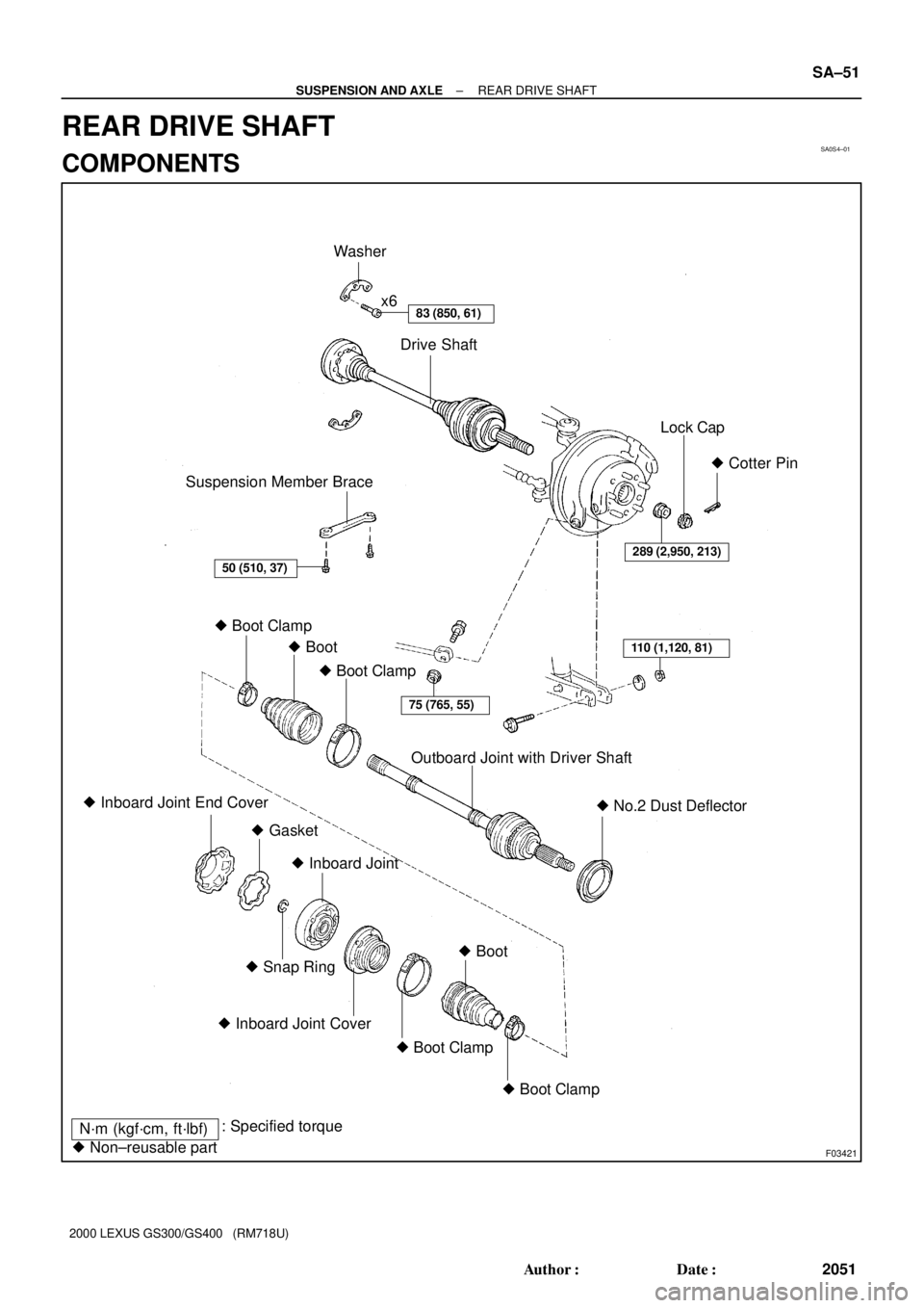
Suspension Member BraceDrive Shaft x6
Lock Cap
Outboard Joint with Driver Shaft� Cotter Pin
� Boot Clamp
� No.2 Dust Deflector � Inboard Joint End Cover
� GasketWasher
289 (2,950, 213)
110 (1,120, 81)
75 (765, 55)
� Boot Clamp � Boot
� Snap Ring
� Inboard Joint Cover
� Boot Clamp � Boot Clamp� Boot � Inboard Joint
N´m (kgf´cm, ft´lbf): Specified torque
� Non±reusable part
83 (850, 61)
50 (510, 37)
± SUSPENSION AND AXLEREAR DRIVE SHAFT
SA±51
2051 Author�: Date�:
2000 LEXUS GS300/GS400 (RM718U)
REAR DRIVE SHAFT
COMPONENTS
Page 1065 of 1111

REMOVAL
1. REMOVE REAR WHEEL
Torque: 103 N´m (1,050")
SA0S5±03
F02394
Matchmarks
F03449
Matchmarks
SA±52
± SUSPENSION AND AXLEREAR DRIVE SHAFT
2052 Author�: Date�:
2000 LEXUS GS300/GS400 (RM718U)
REMOVAL
1. REMOVE REAR WHEEL
Torque: 103 N´m (1,050 kgf´cm, 76 ft´lbf)
2. REMOVE SUSPENSION MEMBER BRACE
Remove the 2 bolts and suspension member brace.
Torque: 50 N´m (510 kgf´cm, 37 ft´lbf)
3. REMOVE COTTER PIN, LOCK CAP AND LOCK NUT
(a) Remove the cotter pin and lock cap.
(b) With depressing the brake pedal, remove the nut.
Torque: 289 N´m (2,950 kgf´cm, 213 ft´lbf)
4. REMOVE DRIVE SHAFT
(a) Place matchmarks on the adjusting cam and lower sus-
pension arm.
(b) Remove the bolt and nut, disconnect the No.2 lower sus-
pension arm from the axle hub.
Torque: 110 N´m (1,120 kgf´cm, 81 ft´lbf)
(c) Remove the bolt and nut, disconnect the No.1 lower sus-
pension arm from the axle hub.
Torque: 75 N´m (765 kgf´cm, 55 ft´lbf)
(d) Place matchmarks on the drive shaft and side gear shaft.
NOTICE:
Do not punch to mark the matchmarks. Use paint etc.
(e) Using a 10 mm hexagon wrench, remove the 6 hexagon
bolts and 2 washers with depressing the brake pedal.
Torque: 83 N´m (850 kgf´cm, 61 ft´lbf)
HINT:
At the time of installation, apply a light coat of engine oil on the
threads of the bolts.
(f) Hold the inboard joint side of the drive shaft so that the
outboard joint side does not bend too much.
Page 1073 of 1111
SA0S9±01
F03422
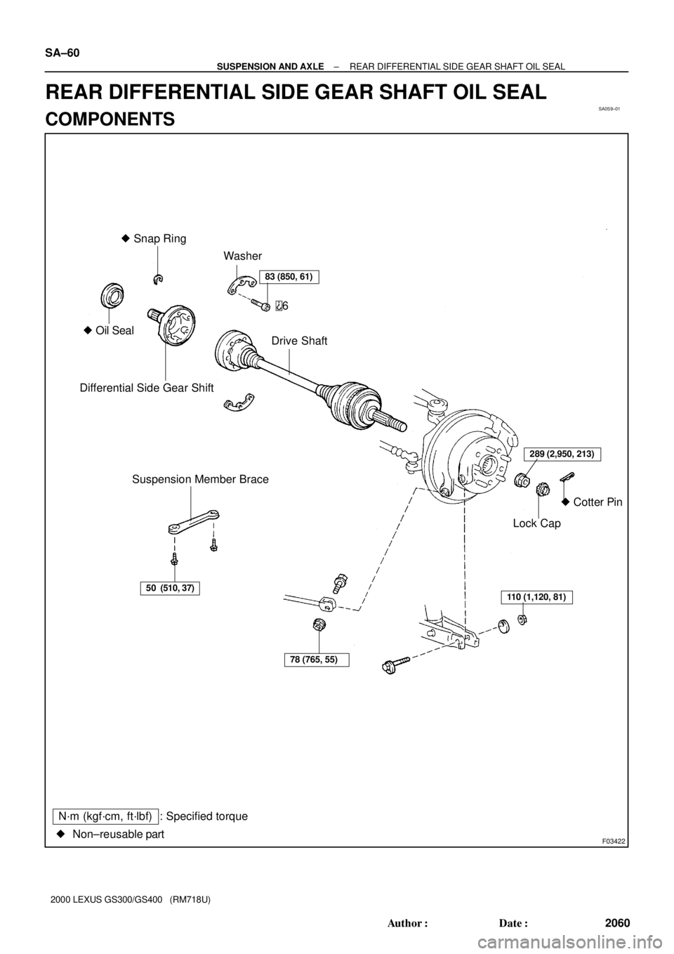
Suspension Member Brace Differential Side Gear ShiftDrive Shaft Washer
� Cotter Pin � Snap Ring
� Oil Seal
6
83 (850, 61)
78 (765, 55)
110 (1,120, 81)
Lock Cap
��Non±reusable part: Specified torque
N´m (kgf´cm, ft´lbf)
50 (510, 37)
289 (2,950, 213)
SA±60
± SUSPENSION AND AXLEREAR DIFFERENTIAL SIDE GEAR SHAFT OIL SEAL
2060 Author�: Date�:
2000 LEXUS GS300/GS400 (RM718U)
REAR DIFFERENTIAL SIDE GEAR SHAFT OIL SEAL
COMPONENTS
Page 1089 of 1111

R15897
SST
SST SA±74
± SUSPENSION AND AXLEREAR DIFFERENTIAL CARRIER
2074 Author�: Date�:
2000 LEXUS")
SA1143
Boiling Water
SA1158
Matchmarks
SA1148
SA1180
60 ± 90° 64 N´m (650 kgf´cm, 47 ft´lbf)
R15897
SST
SST SA±74
± SUSPENSION AND AXLEREAR DIFFERENTIAL CARRIER
2074 Author�: Date�:
2000 LEXUS GS300/GS400 (RM718U)
3. INSTALL RING GEAR ON DIFFERENTIAL CASE
(a) Clean the contact surfaces of the differential case and the
threads of the ring gear and differential case.
(b) Heat the ring gear in boiling water.
(c) Carefully remove the ring gear from the boiling water.
(d) After the moisture on the ring gear has completely evapo-
rated, quickly install the ring gear to the differential case.
HINT:
Align the matchmarks on the ring gear and the differential case.
(e) Tighten 2 of the bolts temporarily so that the bolt holes in
the ring gear and differential case are not misaligned.
NOTICE:
The ring gear set bolts should not be tightened until the
ring gear has cooled sufficiently.
4. INSTALL RING GEAR SET BOLTS
(a) After the ring gear has cooled sufficiently, install new 10
ring gear set bolts to which thread lock has been applied.
Thread lock:
Part No. 08833±00100, THREE BOND 1360 K or equiv-
alent.
NOTICE:
New ring gear set bolts should be used in every case.
(b) Torque the 10 set bolts uniformly and a little at a time.
Torque: 64 N´m (650 kgf´cm, 47 ft´lbf)
(c) Tighten the bolts further by 60 ± 90°.
NOTICE:
Tighten the bolts in diagonally opposite pairs.
5. INSTALL SIDE BEARINGS
Using SST and a press, install the 2 side bearings.
SST 09710±30050, 09950±60010 (09951±00450),
09950±70010 (09951±07150)
Page 1105 of 1111
SA0SP±01
F03424
Upper Suspension Arm
64 (650, 47)
88 (900, 65)
18 (185, 13)
88 (900, 65)
Shock Absorber With
Coil Spring
Washer
Drive Shaft
Suspension Member Brace
110 (1,120, 81)
30 (305, 22)
289 (2,950, 213)
50 (510, 37)
X6
HID Type Headlight:
Height Control
Sensor Link
N´m (kgf´cm, ft´lbf) : Specified torque
� Non±reusable part� Cotter Pin
Lock Cap
110 (1,120, 81)
110 (1,120, 81)
No.2 Lower Suspension Arm
83 (850, 61)
108 (1,100, 80)
75 (765, 55)
± SUSPENSION AND AXLEREAR UPPER SUSPENSION ARM
SA±93
2093 Author�: Date�:
2000 LEXUS GS300/GS400 (RM718U)
REAR UPPER SUSPENSION ARM
COMPONENTS


88 (900, 65)
18 (185, 13)
88 (900, 65)
Shock Absorber With
Coil Spring
Washer
Drive Shaft
Suspension Member Brace
110 (1,120, 81)
30 (305, 22)
289 (2")