Page 1059 of 1111

REMOVAL
1. REMOVE REAR WHEEL
Torque: 103 N´m (1,050 kgf´cm, 76 ft´lbf)")
SA0RZ±01
F02396
F02326
SA±44
± SUSPENSION AND AXLEREAR AXLE CARRIER
2044 Author�: Date�:
2000 LEXUS GS300/GS400 (RM718U)
REMOVAL
1. REMOVE REAR WHEEL
Torque: 103 N´m (1,050 kgf´cm, 76 ft´lbf)
2. REMOVE ABS SPEED SENSOR
Torque: 7.8 N´m (80 kgf´cm, 69 in.´lbf)
3. REMOVE REAR BRAKE CALIPER AND DISC
(a) Remove the 2 bolts and brake caliper from the axle hub.
(b) Support the brake caliper securely.
(c) Remove the disc.
4. CHECK BEARING BACKLASH AND AXLE HUB DEVI-
ATION
(a) Using a dial indicator near the center of the axle hub and
check the backlash in the bearing shaft direction.
Maximum: 0.05 mm (0.0020 in.)
If the backlash exceeds the specified maximum, replace the
bearing.
(b) Using a dial indicator, check the deviation at the surface
of the axle hub outside the hub bolt.
Maximum: 0.07 mm (0.0028 in.)
If the deviation exceeds the specified maximum, replace the
axle hub.
5. INSTALL DISC AND BRAKE CALIPER
(a) Install the disc.
(b) Install the brake caliper and 2 bolts to the axle carrier.
Torque: 104 N´m (1,065 kgf´cm, 77 ft´lbf)
6. REMOVE DRIVE SHAFT (See page SA±52)
7. REMOVE BRAKE CALIPER AND DISC (See step 2)
8. REMOVE PARKING BRAKE SHOE
(See page BR±33)
9. DISCONNECT PARKING BRAKE CABLE
Remove the 2 bolts and disconnect the parking brake cable.
Torque: 7.8 N´m (80 kgf´cm, 69 in.´lbf)
10. DISCONNECT UPPER SUSPENSION ARM FROM
AXLE CARRIER
(a) Remove the nut.
Torque: 108 N´m (1,100 kgf´cm, 80 ft´lbf)
Page 1065 of 1111

REMOVAL
1. REMOVE REAR WHEEL
Torque: 103 N´m (1,050")
SA0S5±03
F02394
Matchmarks
F03449
Matchmarks
SA±52
± SUSPENSION AND AXLEREAR DRIVE SHAFT
2052 Author�: Date�:
2000 LEXUS GS300/GS400 (RM718U)
REMOVAL
1. REMOVE REAR WHEEL
Torque: 103 N´m (1,050 kgf´cm, 76 ft´lbf)
2. REMOVE SUSPENSION MEMBER BRACE
Remove the 2 bolts and suspension member brace.
Torque: 50 N´m (510 kgf´cm, 37 ft´lbf)
3. REMOVE COTTER PIN, LOCK CAP AND LOCK NUT
(a) Remove the cotter pin and lock cap.
(b) With depressing the brake pedal, remove the nut.
Torque: 289 N´m (2,950 kgf´cm, 213 ft´lbf)
4. REMOVE DRIVE SHAFT
(a) Place matchmarks on the adjusting cam and lower sus-
pension arm.
(b) Remove the bolt and nut, disconnect the No.2 lower sus-
pension arm from the axle hub.
Torque: 110 N´m (1,120 kgf´cm, 81 ft´lbf)
(c) Remove the bolt and nut, disconnect the No.1 lower sus-
pension arm from the axle hub.
Torque: 75 N´m (765 kgf´cm, 55 ft´lbf)
(d) Place matchmarks on the drive shaft and side gear shaft.
NOTICE:
Do not punch to mark the matchmarks. Use paint etc.
(e) Using a 10 mm hexagon wrench, remove the 6 hexagon
bolts and 2 washers with depressing the brake pedal.
Torque: 83 N´m (850 kgf´cm, 61 ft´lbf)
HINT:
At the time of installation, apply a light coat of engine oil on the
threads of the bolts.
(f) Hold the inboard joint side of the drive shaft so that the
outboard joint side does not bend too much.
Page 1106 of 1111
SA0SQ±01
F02383
SST
F02384
SA±94
± SUSPENSION AND AXLEREAR UPPER SUSPENSION ARM
2094 Author�: Date�:
2000 LEXUS GS300/GS400 (RM718U)
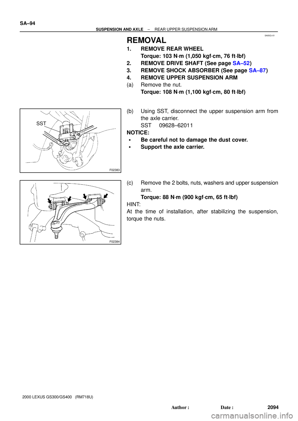
REMOVAL
1. REMOVE REAR WHEEL
Torque: 103 N´m (1,050 kgf´cm, 76 ft´lbf)
2. REMOVE DRIVE SHAFT (See page SA±52)
3. REMOVE SHOCK ABSORBER (See page SA±87)
4. REMOVE UPPER SUSPENSION ARM
(a) Remove the nut.
Torque: 108 N´m (1,100 kgf´cm, 80 ft´lbf)
(b) Using SST, disconnect the upper suspension arm from
the axle carrier.
SST 09628±62011
NOTICE:
�Be careful not to damage the dust cover.
�Support the axle carrier.
(c) Remove the 2 bolts, nuts, washers and upper suspension
arm.
Torque: 88 N´m (900 kgf´cm, 65 ft´lbf)
HINT:
At the time of installation, after stabilizing the suspension,
torque the nuts.
Page 1110 of 1111

REMOVAL
1. REMOVE REAR WHEEL
Torque: 103 N´m (1,050 kgf´c")
SA0SU±01
F02385
F02386
F02387
SA±98
± SUSPENSION AND AXLEREAR LOWER SUSPENSION ARM
2098 Author�: Date�:
2000 LEXUS GS300/GS400 (RM718U)
REMOVAL
1. REMOVE REAR WHEEL
Torque: 103 N´m (1,050 kgf´cm, 76 ft´lbf)
2. REMOVE REAR FENDER APRON SEAL
3. REMOVE NO.1 LOWER SUSPENSION ARM
Remove the 2 bolts, nuts, and No.1 lower suspension arm.
Torque: 75 N´m (765 kgf´cm, 55 ft´lbf)
HINT:
At the time of installation, after stabilizing the suspension,
torque the nuts.
4. REMOVE NO.2 LOWER SUSPENSION ARM
(a) Halogen type headlight:
Remove the bolt, nut and disconnect the stabilizer bar link
from the No.2 lower suspension arm.
Torque: 30 N´m (305 kgf´cm, 22 ft´lbf)
(b) HID type headlight:
Remove the bolt, nut and disconnect the stabilizer bar link
and the height control link from the No.2 lower suspen-
sion arm.
Torque: 30 N´m (305 kgf´cm, 22 ft´lbf)
(c) Remove the bolt, nut and disconnect the shock absorber
from the No.2 lower suspension arm.
Torque: 110 N´m (1,120 kgf´cm, 81 ft´lbf)
HINT:
At the time of installation, after stabilizing the suspension,
torque the nut.
Page:
< prev 1-8 9-16 17-24