Page 532 of 1111
EM0D9±04
A09751
Air Cleaner,
MAF Meter
and Intake Air
Resonator
Assembly
PCV HoseExhaust Manifold
Case Clamp
PS Air
Hose
EVAP Hose
Air Cleaner InletMAF Meter
Connector
Heated Oxygen Sensor
Connector
� Clamp
40 (408, 32)
x 8
� Gasket
44 (440, 32)
44 (440, 32)
Pipe Support Bracket
Accelerator Cable
� Gasket
Upper Radiator
Hose
Front Exhaust Pipe
Drive Belt
Engine Under Cover
x 18
N´m (kgf´cm, ft´lbf) : Specified torque
� Non±reusable Part
Engine Cover
± ENGINE MECHANICAL (2JZ±GE)CYLINDER HEAD
EM±29
1383 Author�: Date�:
2000 LEXUS GS300/GS400 (RM718U)
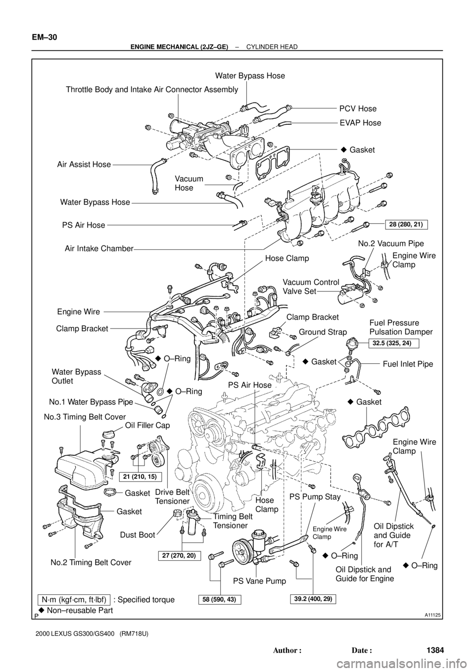
CYLINDER HEAD
COMPONENTS
Page 533 of 1111
A11125
Throttle Body and Intake Air Connector AssemblyWater Bypass Hose
PCV Hose
EVAP Hose
� Gasket
Air Assist Hose
Vacuum
Hose
PS Air Hose
Air Intake Chamber
Engine Wire
Clamp
Drive Belt
TensionerClamp Bracket
Ground StrapFuel Pressure
Pulsation Damper Clamp Bracket
Water Bypass
Outlet
No.1 Water Bypass Pipe
No.3 Timing Belt Cover� O±Ring
Oil Filler CapFuel Inlet Pipe
PS Air Hose
Hose
Clamp
Timing Belt
Tensioner
PS Pump Stay
Oil Dipstick
and Guide
for A/T
PS Vane Pump Water Bypass Hose
28 (280, 21)
Engine Wire
� O±Ring
No.2 Timing Belt Cover
GasketGasket
21 (210, 15)
32.5 (325, 24)
� Gasket
� Gasket
Engine Wire
Clamp
� O±Ring � O±RingOil Dipstick and
Guide for Engine
27 (270, 20)
58 (590, 43)39.2 (400, 29)N´m (kgf´cm, ft´lbf) : Specified torque
� Non±reusable Part
Dust BootEngine Wire
Clamp
No.2 Vacuum Pipe
Hose Clamp
Vacuum Control
Valve Set
EM±30
± ENGINE MECHANICAL (2JZ±GE)CYLINDER HEAD
1384 Author�: Date�:
2000 LEXUS GS300/GS400 (RM718U)
Page 534 of 1111
A11124
Ignition Coils and
High±Tension Cord
Assembly
GasketNo.2 Cylinder Head Cover
Camshaft Timing Oil Control ValveExhaust Camshaft
No.1 Camshaft Bearing Cap
Gasket
No.1 Cylinder Head Cover
No.2 Camshaft Bearing Cap x 6
x 24 x 6
20 (200, 15)
20 (200, 15)
Intake Camshaft
� O±Ring
� GasketOil Control Valve Filter
x 14 No.3 Camshaft Bearing Cap
No.1 Oil Pipe
See page EM±52
1st 35 (350, 25)
2nd Turn 90°
3rd Turn 90°
Heater Hose
55 (550, 41)
Union Bolt
18 (180, 13)Spark Plug
� Oil Seal
No.4 Timing Belt Cover
Camshaft Timing Pulley
Cylinder Head Assembly
Intake Manifold Assembly
Manifold Stay
� Cylinder Head Gasket
� Gasket
x 7
81 (810, 60)
15 (150, 11)
8.0 (80, 71 in.´lbf)
N´m (kgf´cm, ft´lbf) : Specified torque
� Non±reusable partx 12
28 (280, 21)
Starter Wire
Straight
Screw Plug
Timing Belt
± ENGINE MECHANICAL (2JZ±GE)CYLINDER HEAD
EM±31
1385 Author�: Date�:
2000 LEXUS GS300/GS400 (RM718U)
Page 538 of 1111
CYLINDER HEAD
EM±33
1387 Author�: Date�:
2000 LEXUS GS300/GS400 (RM718U)
REMOVAL
1. REMOVE ENGINE UNDER COVER
2. DRAI")
EM0DA±03
A02823
A02802
B01935
Wire
Grommet
Clamp
± ENGINE MECHANICAL (2JZ±GE)CYLINDER HEAD
EM±33
1387 Author�: Date�:
2000 LEXUS GS300/GS400 (RM718U)
REMOVAL
1. REMOVE ENGINE UNDER COVER
2. DRAIN ENGINE COOLANT
3. DISCONNECT UPPER RADIATOR HOSE FROM WA-
TER OUTLET
4. REMOVE ENGINE COVER
Remove the 4 nuts and engine cover.
5. REMOVE AIR CLEANER INLET
6. REMOVE AIR CLEANER, MAF METER AND INTAKE
AIR RESONATOR ASSEMBLY (See page EM±62)
7. REMOVE DRIVE BELT (See page CH±1)
8. DISCONNECT PS PUMP WITHOUT DISCONNECTING
HOSES
(a) Disconnect the PS air hose from the No.4 timing belt cov-
er.
(b) Disconnect the PS air hose from the air intake chamber.
(c) Remove the 2 bolts and pump rear stay.
(d) Remove the 2 bolts, and disconnect the vane pump from
the pump bracket.
HINT:
Put aside the vane pump, and suspend it.
9. DISCONNECT FRONT EXHAUST PIPE FROM EX-
HAUST MANIFOLD
(a) Disconnect the wire grommet and sensor wire of the
heated oxygen sensor (bank 2 sensor 2) from the hole
and clamp on the floor.
Page 539 of 1111
CYLINDER HEAD
1388 Author�: Date�:
2000 LEXUS GS300/GS400 (RM718U)
(b) Remove the 3 bolts and nuts holding the front exhaust
pipe to the exh")
A02819
A09752
A02735
EM±34
± ENGINE MECHANICAL (2JZ±GE)CYLINDER HEAD
1388 Author�: Date�:
2000 LEXUS GS300/GS400 (RM718U)
(b) Remove the 3 bolts and nuts holding the front exhaust
pipe to the exhaust manifold.
(c) Remove the 2 bolts and pipe support bracket.
(d) Disconnect the front exhaust pipe from the exhaust man-
ifold, and remove the 2 gaskets.
10. REMOVE EXHAUST MANIFOLD
(a) Disconnect the 3 heated oxygen sensor connectors and
clamp.
(b) Remove the clamp and case clamp.
(c) Using a 14 mm deep socket wrench, remove the 8 nuts,
exhaust manifold and 2 gaskets.
11. REMOVE WATER BYPASS OUTLET AND NO.1
WATER BYPASS PIPE (See page CO±11)
12. REMOVE THROTTLE BODY AND INTAKE AIR
CONNECTOR ASSEMBLY (See page EM±5)
13. REMOVE OIL DIPSTICK AND GUIDE FOR ENGINE
(See page LU±6)
14. REMOVE OIL DIPSTICK AND GUIDE FOR A/T
(See page EM±62)
15. REMOVE AIR INTAKE CHAMBER (See page SF±46)
16. REMOVE VACUUM CONTROL VALVE SET AND NO.2
VACUUM PIPE
(a) Disconnect the VSV connector for the ACIS.
(b) Remove the 3 nuts, vacuum control valve set and No.2
vacuum pipe.
(c) Disconnect the engine wire clamp from the clamp bracket
of the No.2 vacuum pipe.
17. REMOVE NO.3 TIMING BELT COVER
18. REMOVE IGNITION COILS AND HIGH±TENSION
CORD SET ASSEMBLY (See page IG±7)
19. REMOVE SPARK PLUGS
Page 540 of 1111

(b) (c)
(d)(d)
(c) (b)
A02811
A02733
Clamp Bracket
A11123
5 mm
Hexagon
Wrench
± ENGINE MECHANICAL (2JZ±GE)CYLINDER HEAD
EM±35
1389 Author�: Date�:
2000 LEXUS GS300/GS400 (RM718U)
20. D")
A02732
(a)
(b) (c)
(d)(d)
(c) (b)
A02811
A02733
Clamp Bracket
A11123
5 mm
Hexagon
Wrench
± ENGINE MECHANICAL (2JZ±GE)CYLINDER HEAD
EM±35
1389 Author�: Date�:
2000 LEXUS GS300/GS400 (RM718U)
20. DISCONNECT ENGINE WIRE FROM CYLINDER HEAD
(a) Disconnect the ground strap from the cylinder head.
(b) Disconnect the 2 water bypass hoses from the hose
clamps on the cylinder head and oil filter bracket.
(c) Remove the 2 bolts and hose clamps.
(d) Disconnect the heated oxygen sensor (bank 2 sensor 1)
connector and engine wire clamp from the hose clamps.
(e) Disconnect the heated oxygen sensor (bank 1 sensor 1)
connector.
(f) Disconnect the crankshaft position sensor connector.
(g) Disconnect the generator connector.
(h) Remove the bolt and clamp bracket, and disconnect the
engine wire from the water pump.
(i) Disconnect the 2 ground terminals from the intake man-
ifold.
(j) Disconnect the 2 engine wire clamps from the No.1 oil
pipe and clamp bracket on the intake manifold.
(k) Remove the bolt and clamp bracket.
(l) Disconnect the ECT sensor connector.
(m) Remove the 2 knock sensor connectors.
(n) Remove the oil pressure switch connector.
(o) Remove the oil level sensor connector.
(p) Remove the starter connector.
(q) Remove the 6 injector connectors.
(r) Remove the camshaft timing oil control valve connector.
(s) Remove the camshaft position sensor connector.
(t) Using a 5 mm hexagon wrench, remove the bolt holding
the engine wire protector to the No.2 cylinder head cover.
(u) Remove the 3 nuts, and disconnect the engine wire pro-
tector from the intake manifold.
21. REMOVE FUEL PRESSURE PULSATION DAMPER
(See page SF±26)
Page 541 of 1111
CYLINDER HEAD
1390 Author�: Date�:
2000 LEXUS GS300/GS400 (RM718U)
22. REMOVE INTAKE MANIFOLD ASSEMBLY
(a) Disconnect the star")
A11122
A02713
A02836
S03013
A02647
EM±36
± ENGINE MECHANICAL (2JZ±GE)CYLINDER HEAD
1390 Author�: Date�:
2000 LEXUS GS300/GS400 (RM718U)
22. REMOVE INTAKE MANIFOLD ASSEMBLY
(a) Disconnect the starter wire from the manifold stay.
(b) Remove the 2 bolts and manifold stay.
(c) Remove the 7 bolts, 2 nuts, intake manifold and delivery
pipe assembly and gasket.
23. REMOVE NO.1 AND NO.2 CYLINDER HEAD COVERS
(a) Remove the 12 bolts and 4 nuts.
(b) Remove the cylinder head covers and gaskets.
24. DISCONNECT TIMING BELT FROM CAMSHAFT TIM-
ING PULLEYS (See page EM±16)
NOTICE:
�Support the timing belt, so that the measuring of the
crankshaft timing pulley and timing belt does not
shift.
�Be careful not to drop anything inside the timing belt
cover.
�Do not allow the timing belt to come into contact with
oil, water or dust.
25. REMOVE CAMSHAFT TIMING PULLEYS
(a) Remove the exhaust camshaft timing pulley.
Hold the hexagon portion of the camshaft with a wrench, and
remove the pulley bolt and camshaft pulley.
(b) Remove the VVT±i (intake camshaft timing) pulley.
(See page EM±16)
26. REMOVE NO.4 TIMING BELT COVER
Remove the 4 bolts and timing belt cover.
Page 542 of 1111
CYLINDER H")
A02695
5 mm Hexagon
Wrench
A02696
No.1
No.3
A02930
110
211
12
5
67
83
49
1
2
11
12
5
6
7
8
3
4910
S02650
10 mm
Bi±Hexagon
Wrench
3
14 12 13 10 11 762
15 9 8 4
± ENGINE MECHANICAL (2JZ±GE)CYLINDER HEAD
EM±37
1391 Author�: Date�:
2000 LEXUS GS300/GS400 (RM718U)
27. REMOVE CAMSHAFTS
(a) Using a 5 mm hexagon wrench, the 2 No.3 camshaft
bearing cap bolts.
(b) Uniformly loosen and remove the 4 camshaft bearing cap
bolts.
(c) Using a screwdriver, pry out the Nos.1, 3 camshaft bear-
ing caps and oil seals.
NOTICE:
Be careful not to damage the cap. Tape the screwdriver tip.
(d) Uniformly loosen and remove the 12 camshaft bearing
cap bolts, in several passes, in the sequence shown.
(e) Remove the 6 No.2 camshaft bearing caps and camshaft.
Remove the intake and exhaust camshafts.
28. REMOVE CYLINDER HEAD ASSEMBLY
(a) Using a 10 mm bi±hexagon wrench, uniformly loosen and
remove the 14 cylinder head bolts, in several passes, in
the sequence shown.
NOTICE:
Cylinder head warpage or cranking could result from re-
moving in incorrect order.
(b) Remove the 14 plate washers.