Page 1091 of 1395
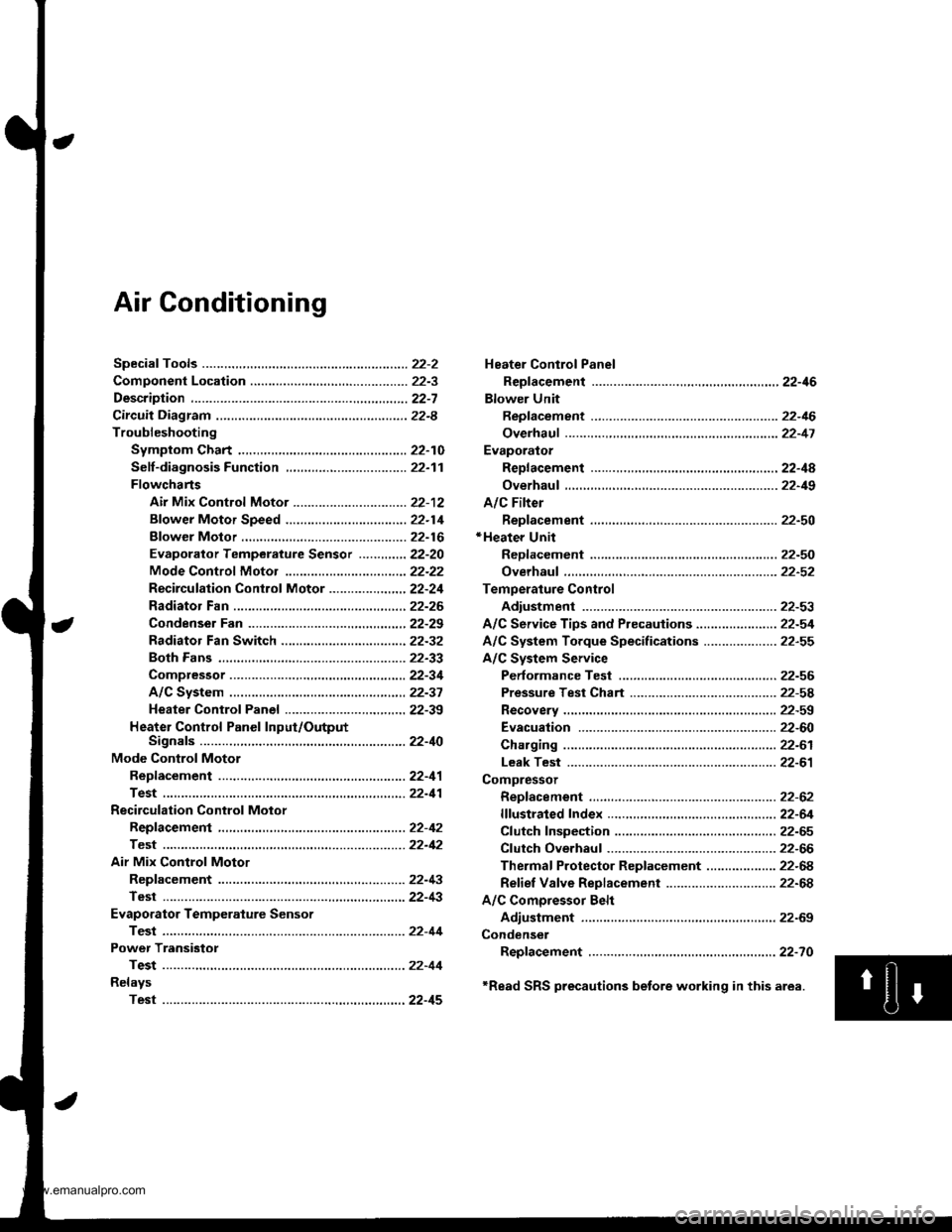
Air Conditioning
Heater Control Panel
Reofacement ,.,...,,.,..,.,.,,22-46
Blower Unit
Replacement .................. 22-46
Overhaul ...........,,,., .......-.22-17
Evaporalor
ReDlacement ...,.,.,..,......,22-4A
Overhaul ................ .........22-19
A/C Filter
Replacement ..................22-50*Heater Unit
ReDfacement ..................22-50
Overhaul ..,.,..,.,...,.. .........22-52
Temperature Control
Adiustment ....................22-53
A/C Service Tips and Precauiions............-....-.... 22-54
A/C System Torque Specifications .................... 22-55
A/C System Service
Performance Test ......,...22-56
Pressure Test Chart .-.....22-5a
Recovery ..............,. ...-.-...22-59
Evacuation -...........-........22-60
Charging ................ .......-.22-61
Leak Test ........................22-61
Compressor
Repfacement ..........-.......22-62
flfustrated Index .....,.......22-64
Cfutch fnspection .........,.22-65
Cfutch Overhaul ............- 22-66
Thermaf Protector Rep|acement ................... 22-68
Refief Valve Replacement .............................. 22-68
A/C Comoressor Belt
Adiustment .................... 22-69
Condenser
Repfacement .,.....,,.,..,.,..22-70
'Read SRS precautions betore working in this area.
www.emanualpro.com
Page 1096 of 1395
Component Location
Index (cont'dl
SRS components are located in this area. Review the SRS component locations, precautions, and procedures in the SRS
section (24) before performing repairs or service.
BECIRCULATION CONTROL MOTOR4P CONNECTOR
EVAPORATOR TEMPERATURE SENSORTesl, page 22-44POWER TRANSISTOR3P CONNECTOR
AIR MIX CONTROL MOTORReplacement, page 22-43lest, page 22-13
BLOWER MOTOB2P CONNECTOR
BLOWER MOTOR HIGH RELAYTest, page 22-45
HEATER SUB.HARNESS
7P CONNECTOR
DASHBOARD WIRE HARNESS
HEATER CONTROL PANEL8P AND 2OP CONNECYORS
22-6
www.emanualpro.com
Page 1097 of 1395
Description
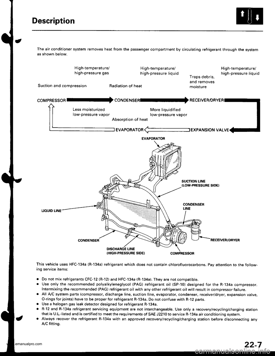
The air conditioner system removes heat from the passenger compartment by circulating refrigerant through the systemas shown below.
High'temperature/ High-temperature/
high-pressure gas h igh-pressure liquid
Suction and compression Radiation of heat
High-temperature/
high-pressu re liq uidr raps oeons,
and removes
motsture
More liquidified
row-pressure vapor
EVAPoRAToR (-l EXPANSToN vAL
SUCTION LINEtLow-PRESSURE S|OEt
LIOUID LINE
CONDENSER
coMpREssoR Il- coruoerusenl* necetve
Less moisturized
low-pressure vapor
Absorption of heat
DISCHARGE LINEIHIGH.PRESSURE SIDEI
This vehicle uses HFC-I34a (R-l34a) refrigerant which does not contain chlorofluorocarbons. Pay attention to the follow-ing service items:
. Do not mix refrigerants CFC-12 (R-12) and HFC-l34a (R-134a). They are not compatible.. Use only the recommended polyalkyleneglycol (PAG) refrigerant oil (SP-10) designed for the R-134a compressor.Intermixing the recommended (PAG) refrigerant oil with any other refrigerant oil will result in compressor failure.. Afl Ay'C system parts (compressor, discharge line. suction line, evaporator, condenser. receiver/dryer, expansion valve,O-rings for joints) have to be proper for refrigerant R-134a. Do not confuse with R-12 parts.
. Use a halogen gas leak detector designed for refrigerant R-134a.. R-12 and R-134a refrigerant servicing equipment are not interchangeable. Use only a recovery/recycling/charging stationthat is U.L.iisted and is certified to meet the requirements of SAE J2210 to service R-134a air conditioning system.. Always recover the refrigerant R-134a with an approved recovery/recycling/charging station before disconnecting anylVC fitting.
EVAPORAYOR
22-7
www.emanualpro.com
Page 1099 of 1395
cnNj@_snN
GRY
PNK/BLK
NED/8LU
REO/YEL
YEL/BLU
8RN/WHT
GRNI/VHT
GRN/RED
POWERTRANSISTOR
c401c402
22-9
4
ORNMHT
Fg"{
EVAPONATORTEMPERATURE SENSOR
fi3'.Hfi|$l#i9D>
"'"-
DASH LTGHTS _/4EE|GHTNESS < l_ REDCONTROLLER -!
REAR
fllf$!S,* (l aLurrLRELAY
O:8P coNNEcToR
n :20P c0NN€CToR
YEL/RED
GRN/YEL
8LU/8LK
BRN
YEL
s5v s coM
AMD P AIR MIXCONTROLMOTOB
HOT
VENT
B/LI/lODEH CONT8OLl
10T0RH/D MDEF
HEATER CONTROL PANEI-
8LK
www.emanualpro.com
Page 1101 of 1395
Self-diagnosis Function
The heater control panel has a self-diagnosis function.
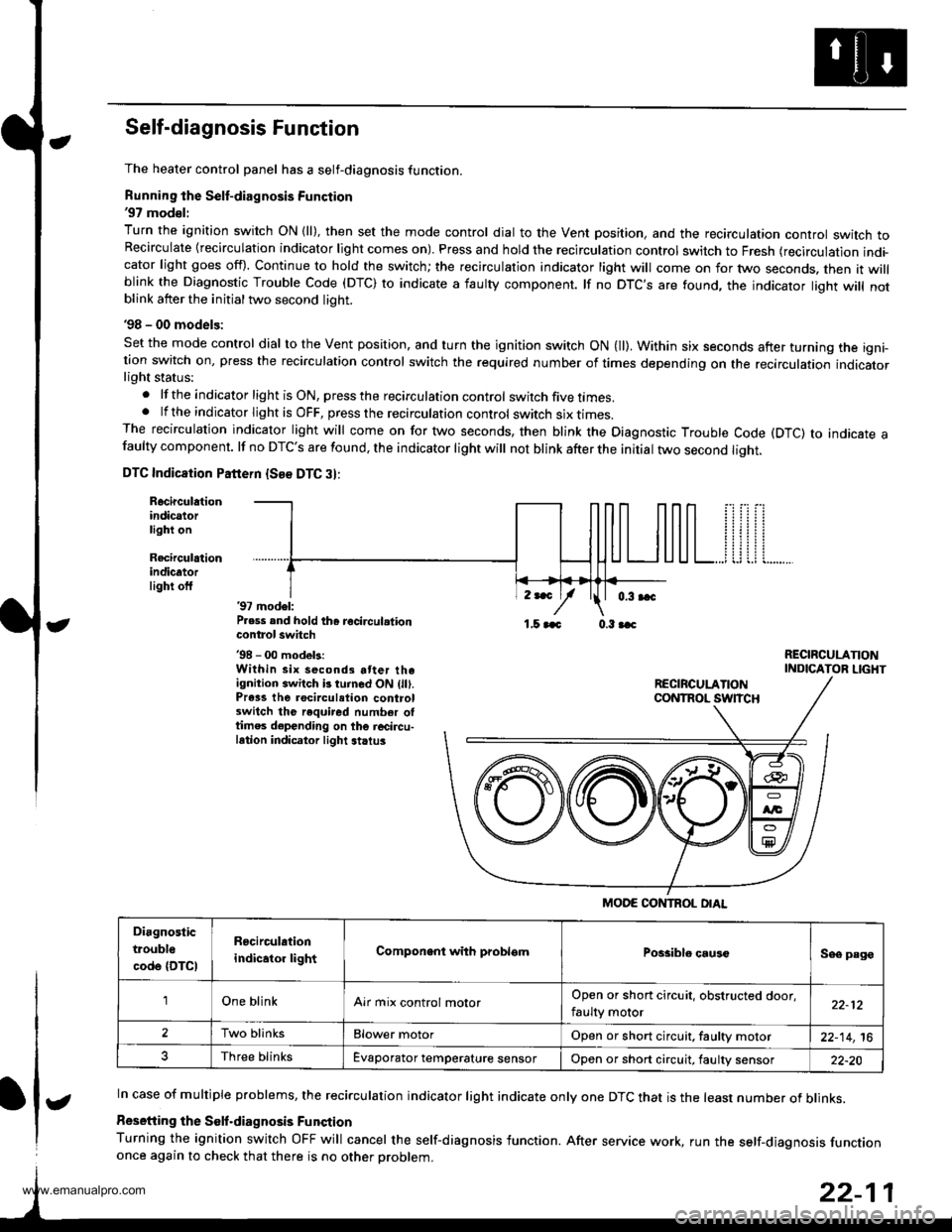
Running the Self-diagnosis Function'97 mod€l:
Turn the ignition switch ON {ll), then set the mode control dial to the Vent position, and the recirculation controt switch toRecirculate {recirculation indicator light comes on). Press and hold the recirculation control switch to Fresh (recirculation indi-cator light goes off). Continue to hold the switch; the recirculation indicator light will come on for two seconds. then it willblink the Diagnostic Trouble Code (DTC) to indicate a iaulty component. lf no DTC'S are found, the indicator liqht will notblink atter the initial two second light.
'98 - 00 models:
Set the mode control dial to the Vent position, and turn the ignition switch ON (ll). Within six seconds after turning the igni-tion switch on, press the recirculation control switch the required number of times depending on the recirculation indicatorlight status:
.lftheindicatorlightisON,presstherecirculationcontrol switch five times..lftheindicatorlightisOFF,presstherecirculationcontrol switch six I|mes.The recirculation indicator light will come on for two seconds, then blink the Diagnostic Trouble Code (DTC) to indicate afaulty component. lf no DTC'S are found, the indicator light will not blink after the initial two second liqht.
DTC Indicaiion Pattern {See DTC 3}:
Rocirculationindicatorlight on
Recirculrtionindicatorlighi off'97 model:P.ess and hold th6 recircul.tioncontrol switch'98 - 00 modek:Within six second3 atter theignition switch b turned ON (lll.Prass the rocirculation controlswitch the required number oltimes depending on the r6circu-lation indicator light striu3
,r*
/1.5 aaa 0.3 aac
RECIRCULANONINDICATOR LIGHT
In case of multiple problems, the recirculation indicator light indicate only one DTC that is the least number of blinks.
Resetiing the Solf.diagnosis Funqtion
Turning the ignition switch OFF will cancel the self-diagnosis function. After service work, run the self-diaqnosis functiononce again to check that there is no other Droblem.
MODE CONTROL OIAL
Diagnostic
trouble
code {DTCI
R6circulation
indicator lightComponent with problsmPossiblo causcSee page
'lOne blinkAir mix control molorOpen or short circuit, obstructed door,
faulty motor22-12
2Two blinksElower motorOpen or short circuit, faultv motor22-14,16
Three blinksEvaporator temperature sensorOpon or short circuit, faulty sensor22-20
t
www.emanualpro.com
Page 1110 of 1395
Troubleshooting
Evaporator Temperature Sensor
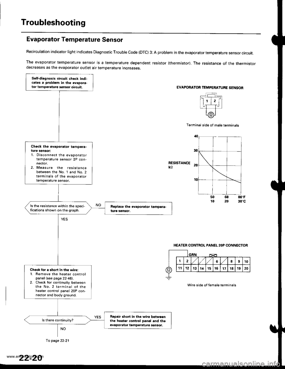
Recirculation indicator light indicates Diagnostic Trouble code (OTC) 3: A problem in the evaporator temperature sensor circuit.
The evaporator temperature sensor is a temperature dependent resistor {thermistor}. The resistance of the thermistordecreases as the evaporator outlet air temperature increases.
EVAPORATOR TEMPEMTURE SENSOR
Terminal side of mal€ terminals
RESISTANCEko
86'F30"c
HEATER CONTROL PANEL 2OP CONNECTOR
Wire side of fema16 terminals
Self-diagnosis circuit check indicates a problem in the avapora-tor tempeleture ssnsor circuit,
Ch€ck the ev.porato. tempera-ture sensor:1. Disconnect the evaporatortemperature sensor 2P con-
2. Measure the resistancebetween the No. 1 and No. 2torminals of the evaporatortemperature sensor.
ls the resistance within the speci,fications shown on the 9raph.
Check lor a short in the wire:l� Remove the heater controlpanel (see page 22-46).2. Check tor continuity betweenthe No.2 terminal ol theheater control panel 20P con,nector and body ground.
Repai. short in the wir6 betwa€nlhe hoater control Danol and theevaporatoa tampereturc senSoa.
fo page 22.21
www.emanualpro.com
Page 1111 of 1395
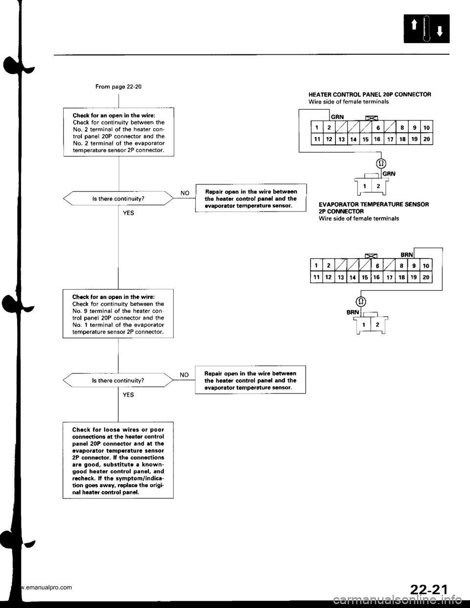
From page 22-20
Chock tor an oDen in th€ wire:Check for continuity betlveen theNo. 2 terminal of the heater con-trol oanel 20P connector and theNo.2 terminal oI the evaporatortemperature sensor 2P connoctor.
Fopair open in the wiro betweentho heato. control penel and theevaporator tempetatule sensor.
Check for rn opsn in tha wiJe:Check for continuity between theNo. 9 terminal of the heater control oanel 20P connector and theNo. 'l terminal ot the evaporatortemperature sensor 2P connector,
Ropair open in tho wire betwegnthe heater control oanel and theevaporator tgmpcrature sen3or.
Chgck fol loose wiros or pool
connectrons at the hoator controloan6l 20P connector and at theeveporator temperatura Sensol2P connector. It the connectionsare good, substitute a known-good he.tel contlol panel, andrech€ck. ll thg symptom/indica-tion 90o3 rwey, roplsce the origi-nal heater control oanel.
HEATER CONTROL PANEL 2OP CONNECTORWire side ol female terminals
EVAPORATOB TEMPERATURE SENSOR2P CONNECTORWire side oI temale terminals
1810
1112131a1516't7181920
GIIN
12,/ l,/689t0
'tl1213lat1516'1718't920
o
+
li-L:t
www.emanualpro.com
Page 1134 of 1395
Evaporator Temperature
SensorPower Transistor
Test
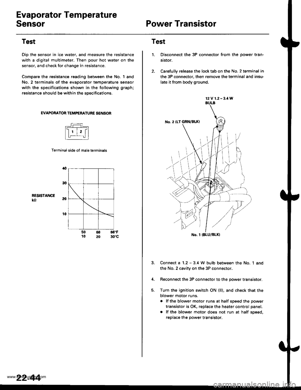
Dip the sensor in ice water, and measure the resistance
with a digital multimeter. Then pour hot water on the
sensor, and check lor change in resistance.
Compare the resistance reading between the No. | 8nd
No. 2 terminals of the evaporator temperature sensor
with the specifications shown in the following graph;
resistance should be within the specifications.
EVAPOBATOR TEMPERATURE SENSOB
Terminal side ol male terminals
4
RESISTANCEko
t0
50 68 86.F10 20 30'c
22-44
12V 1.2-3.1W
No. 2 ILT GRN/BLK)
No. I IBLU/BLK)
Test
1.Disconnect the 3P connector from the oower tran-
st$or.
Carefully release the lock tab on the No. 2 terminal in
the 3P connector, then remove the terminal and insu-
late it from body ground.
Connect a 1.2 - 3.4 W bulb between the No, 1 and
the No,2 cavity on the 3P connectol
Reconnect the 3P connector to the power transistor.
Turn the ignition switch ON (ll). and check that the
blower motor runs.
a lf the blower motor runs at half soeed the oower
transistor is OK, replace the heater control panel.
. lf ths blower motor does not run at half soeed,
reDlaca the Dower transistor.
www.emanualpro.com