2000 HONDA CR-V Temperature
[x] Cancel search: TemperaturePage 277 of 1395
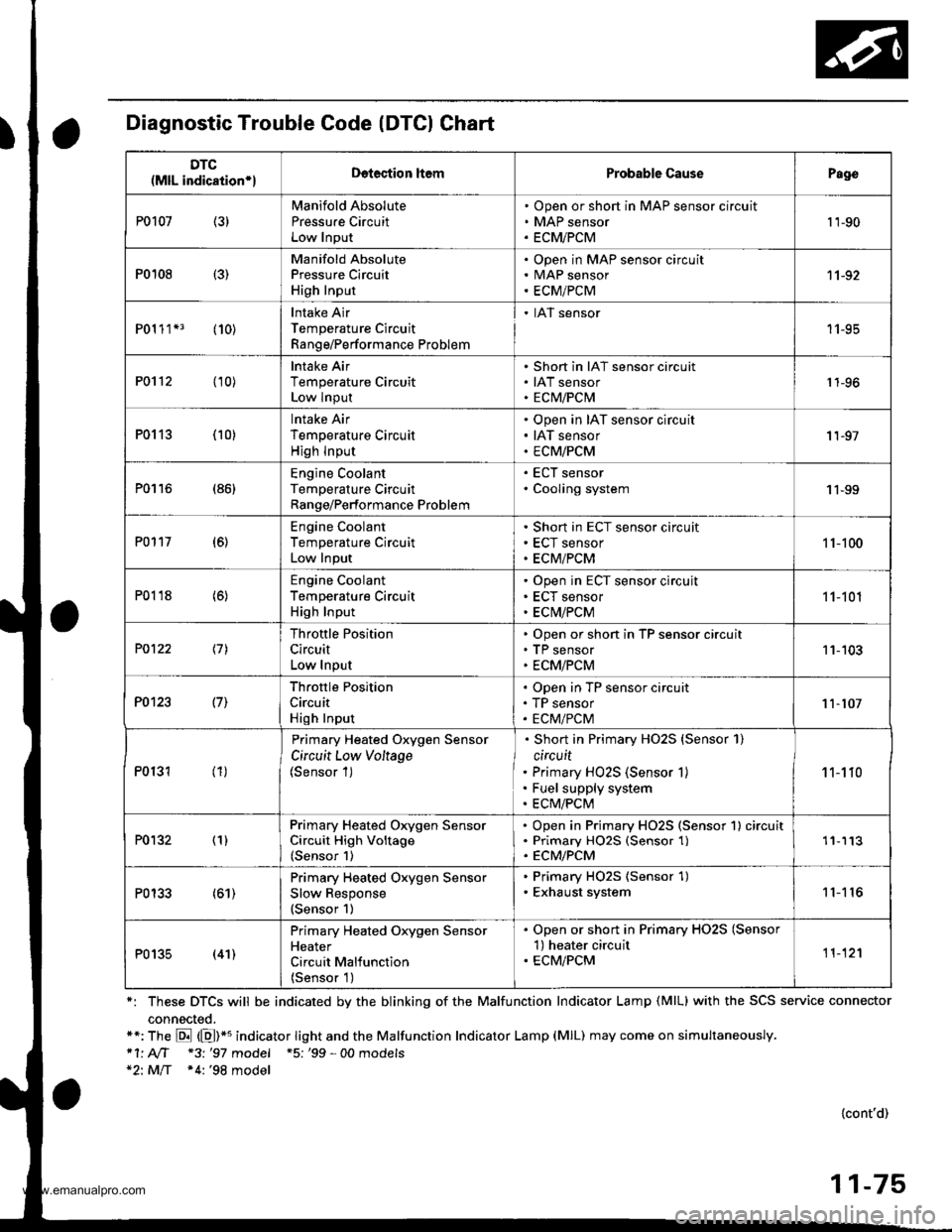
Diagnostic Trouble Code (DTCI Chart
*: These DTCS will be indicated by the blinking of the Malfunction Indicator Lamp (MlL) with the SCS service connector
connected.**: The E (E)*u indicator tight and the Malfunction Indicator Lamp (MlL) may come on simultaneously.*1' AIT *3 '97 model +5; '99 - 00 models*2: MlT *4:'98 model
{cont'd)
11-75
DTC(MlL indication*lDetection ltemProbable CausePago
P0107 (3)Manifold Absolute
Pressu.e CircuitLow Input
Open or short in MAP sensor circuit
MAP sensor
ECMiPCM
't 'l-90
P0108 {3)
Manifold AbsolutePressure Circuit
High Input
Open in MAP sensor circuitMAP sensor
ECM/PCM
11-92
P01 1 1*3 (10)Intake Air
Temperature Circuit
Range/Performance Problem
. IAT sensor
11-95
P0112 (10)lntake Air
Temperature CircuitLow Input
Short in IAT sensor circuit
IAT sensorECM/PCM1 1-96
P0113 (10)lntake Air
Temperature Circuit
High lnput
Open in IAT sensor circuit
IAT sensor
ECM/PCM
'I 1-97
P0116 (86)Engine CoolantTemperature CircuitRange/Performance Problem
ECT sensor
Cooling system1 1-99
P0117 (6)Engine Coolant
Temperature Circuit
Low Input
Short in ECT sensor circuit
ECT sensor
ECM/PCM
1 1-100
P0118 (6)Engine Coolant
Temperature CircuitHigh Input
Open in ECT sensor circujt
ECT sensor
ECM/PCM
11-101
P0122 \11
Throttle Position
Circuit
Low Input
Open or short in TP sensor circuitTP sensor
ECM/PCM
11-103
P0123 l7l
Throftle Position
Circuit
High Input
Open in TP sensor circuit
TP sensor
ECM/PCM11-107
P0131 (1)
Primary Heated Oxygen Sensor
Circuit Low Voltage(Sensor 1)
Short in Primary HO2S {Sensor 1)
circuit
Primary HO2S (Sensor 1)
Fuel supply system
ECM/PCM
1 1-1 10
P0132 (1)Primary Heated Orygen SensorCircuit High Voltage(Sensor 1)
Open in Primary HO2S (Sensor 1) circuitPrimary HO25 (Sensor 1)ECM/PCM
'11113
P0133 (61)Primary Heated Oxygen Sensor
Slow Response(Sensor 1)
. Primary HO2S (Sensor 1). Exhaust system11'I 16
P0135 (41)
Primary Heated Oxygen SensorHeater
Circuit Malfunction
{Sensor 1)
. Open or short in Primary HO2S (Sensor'l) heater circuit. ECM/PCM11-12'l
www.emanualpro.com
Page 282 of 1395

PGM-FI System
System Description
INPUTS
CKP/TDC/CYP Sensor
CKF Sensor
MAP Sensor
ECT Sensor
IAT Sensor
TP Sensor
Primary HO2S
Secondary H02S
vss
KS*5
BARO Sensor
ELD*6
Starter Signal
ALT FR Signal
Air Conditioning Signal
Ay'T Gear Position Signal*1
Baftery Voltage (lGN.1)
Brake Switch Signal
PSP Switch Signal
Fuel Tank Pressuae Sensor*4. *5
Countershaft Speed Sensor*1
Mainshaft Speed Sensor*r
OVER-DRIVE Switch Signal*s
ENGINE CONTROL MODULE (ECM)/
POWERTRAIN CONTROL MODULE (PCM) OUTPUTS
|iuel 1"j""- Th,rhg ""d Drrafr";-l
Et*-.nt"tdt"cont.orl
to,r*,c;;trffi;]
l.----.---:. .Lrgnrnon |lmrng Lonrror I
Ecir/PcM B*k',p Fr""il]
m;"t-ll-r*'io*l
Fuel Injectors
PGM-Fl Main Relay (Fuel Pump)
MIL
IAC Valve
Ay'C Compressor Clutch Relay
Radiator Fan Relay
Condenser Fan Relay
ALT
tcM
EVAP Purge Control Solenoid
Valve
Primary HO2S Heater
Secondary H02S HeaterEVAP Bypass Solenoid Valve*a *5
EVAP Control Canister Vent Shut
DLC
Lock-up Control Solenoid Valve*l
Shift Control Solenoid Valve*1
Ay'T Clutch Pressure Control
Solenoid Valve*1
D4 Indicator Light'1 *3, *a
D Indicator Light,l *5
OVER-DRIVE OFF Indicator
Lighl*t *:
*1: A/T {3:'97 model'2: M/f +4:'98 model*5: '99 - 00 models"6: USA
PGM-Fl System
The PGM-Fl system on this model is a sequential multiport fuel injection system.
Fuel iniecior Timing and Duration
The ECM/PCM contains memories for the basic discharge durations at various engine speeds and manifold pressure. The
basic discharge duration, after being read out from the memory, is further modified by signals sent from various sensors
to obtain the final discharge duration.
ldle Air Control
ldle Air Control Valve (lAC Valve)
When the engine is cold, the Ay'C compressor is on, the transmission is in gear, the brake pedal is depressed, the P/S load
is high, or the alternator is charging, the ECM/PCM controls current to the IAC Valve to maintain the correct idle speed.
lgnition Timing Control
o The ECM/PCM contains memories for basic ionition timing at various engine speeds and manifold air flow rates.
lgnition timing is also adjusted for engine coolant temperature.
. A knock control system was adopted which sets the ideal ig nition timing for the octane rating of the gasoline used.*s
Other Control Funstions
1. Starting Control
When the engine is started. the ECM/PCM provides a rich mixture by increasing fuel injector duration.
2. Fuel Pump Control
. When the ignition switch is initially turned on (ll). the ECMiPCM suppli€s ground to the PGM-FI main relay that
supplies current to the fuel pump for two seconds to pressurize the fuel system.
. When the engine is running, the ECM/PCM supplies ground to the PGM-FI main relay that supplies current to the
fuel oumo.
. When the engine is not running and the ignition is on, the ECM/PCM cuts ground to the PGM-FI main relay which
cuts current to the fuel pump.
1 1-80
www.emanualpro.com
Page 283 of 1395

Fuel Cut-off Control
. During deceleration with the throttle valve closed, current to the fuel injectors iscutoffto improvefuel economyat
speeds over 970 rpm ('97 - 98 models), 920 rpm ('99 - 00 modelsl.
. Fuel cut-off action also takes place when engine speed exceeds 6,500 rpm ('97 - 98 models), 6900 rpm ('99 - 00
models), regardless of the position of the throttle valve, to protect the engine from over-rewing.
With Ay'T model. the PCM cuts the fuel at engine speeds over 5,000 rpm when the vehicle is not moving.*'�
4,./C Comoressor Clutch Relav
When the ECM/PCM receives a demand for cooling from the air conditioning system, it delays the compressor from
being energized, and enriches the mixture to assure a smooth transition to the Ay'C mode.
Evaporative Emission (EVAP) Purge Control Solenoid Valve
When the engine coolant temperature is above 154"F (68'C), the ECM/PCM controls the EVAP purge control solenoid
valve which controls vacuum to the EVAP purge control canister,
Alternator Control
The system controls the voltage generated at the alternator in accordance with the electrical load and driving mode.
which reduces the engine load to improve the fuel economy.
PCM Fail-saf e/Back-up Functions
1. Fail-safe Function
When an abnormality occurs in a signal from a sensor, the ECM/PCM ignores that signal and assumes a pre-pre
grammed value for that sensor that allows the engine to continue to run.
2. Back-up Function
When an abnormality occurs in the ECM/PCM itself, the fuel injectors are controlled by a back-up circuit independent
of the system in order to permit minimal driving.
3. Self-diagnosis Function IMalfunction Indicator Lamp (MlL)l
When an abnormality occurs in a signal from a sensor, the ECM/PCM supplies ground for the MIL and stores the DTC
in erasable memory. When the ignition is initially turned on {ll), the ECM/PCM supplies ground for the MIL for two
seconds to check the MIL bulb condition.
4. Two Trio Detection Method
To prevent false indications, the Two Trip Detection Method is used for the HO2S*1, fuel metering-related. idle control
system, ECT sensor and EVAP control system self-diagnostic functions. When an abnormality occurs, the ECM/PCM
stores it in its memory. When the same abnormality recurs after the ignition switch is turned OFF and ON (ll) again,
the ECM/PCM informs the driver by lighting the MlL. However, to ease troubleshooting, this function is cancelled
when you jump the service check connector, The MIL will then blink immediately when an abnormality occurs.
5. Two (or Three) Driving Cycle Detection Method {'97 model)
A "Driving Cycle" consists of starting the engine, beginning closed loop operation, and stopping the engine. lf misfir-
ing that increases emissions or EVAP control system malfunction is detected during two consecutive driving cycles.
or TWC deterioration is detected during three consecutive driving cycles, the ECM/PCM turns the MIL on. However, to
ease troubleshooting, this function is cancelled when you jump the service check connector. The MIL will then blink
immediately when an abnormality occurs.
*1: '97 - 98 models*2: '99 - 00 models
5.
www.emanualpro.com
Page 297 of 1395
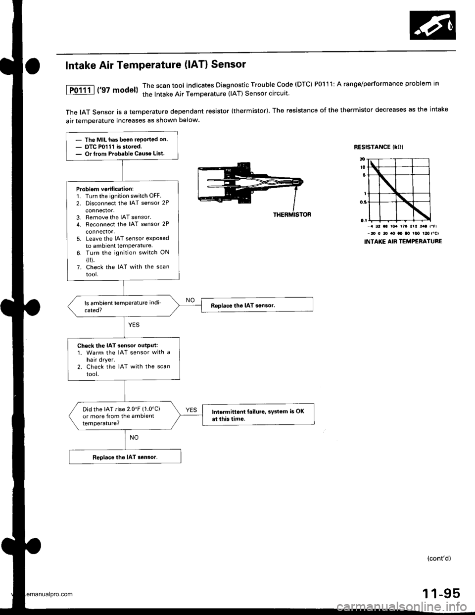
The IAT Sensor is a temperature dependant resistor (thermistor). The resistance of the thermistor decreases as the intake
air temDerature increases as shown below
RESISTANCE IKOI
Intake Air Temperature (lAT) Sensor
1P0111 | ('97 model)The scan tool indicates Diagnostic Trouble code (DTC) P0111: A ranoe/performance problem in
the lntake Air TemDerature (lAT) Sensor circuit.
. 3' aa ro. r?a arl ,.t r.fl20 0 to ao ao aa ioo t2otocl
INTAKE AIB TEMPERATURE
- The MIL has been reported on.- DTC P0111 is stored.- Or lrom Probable Cause List.
Problem vetification:1. Turn the ignition switch OFF.
2. Disconnect the IAT sensor 2P
connector,3. Remove the IAT sensor.4. Reconnect the IAT sensor 2P
connector,5. Leave the IAT sensor etposedto ambient temPerature.6. Turn the ignition switch ON
flr).7. check the IAT with the scan
tool-
R€place the IAT son3or.
Check the IAT sensor output:1. Warm the IAT sensor with ahair dryer.2. Check the IAT with the scan
tool.
Did the IAT rise 2.0'F (1.0'C)
or more from the ambienttemperature?
Intermittent f.ilure, aY3tem is OKai this tim6.
Replace the IAT sensor.
(cont'd)
1 1-95
www.emanualpro.com
Page 298 of 1395
PGM-FI System
Intake Air Temperature (lAT) Sensor (cont'dl
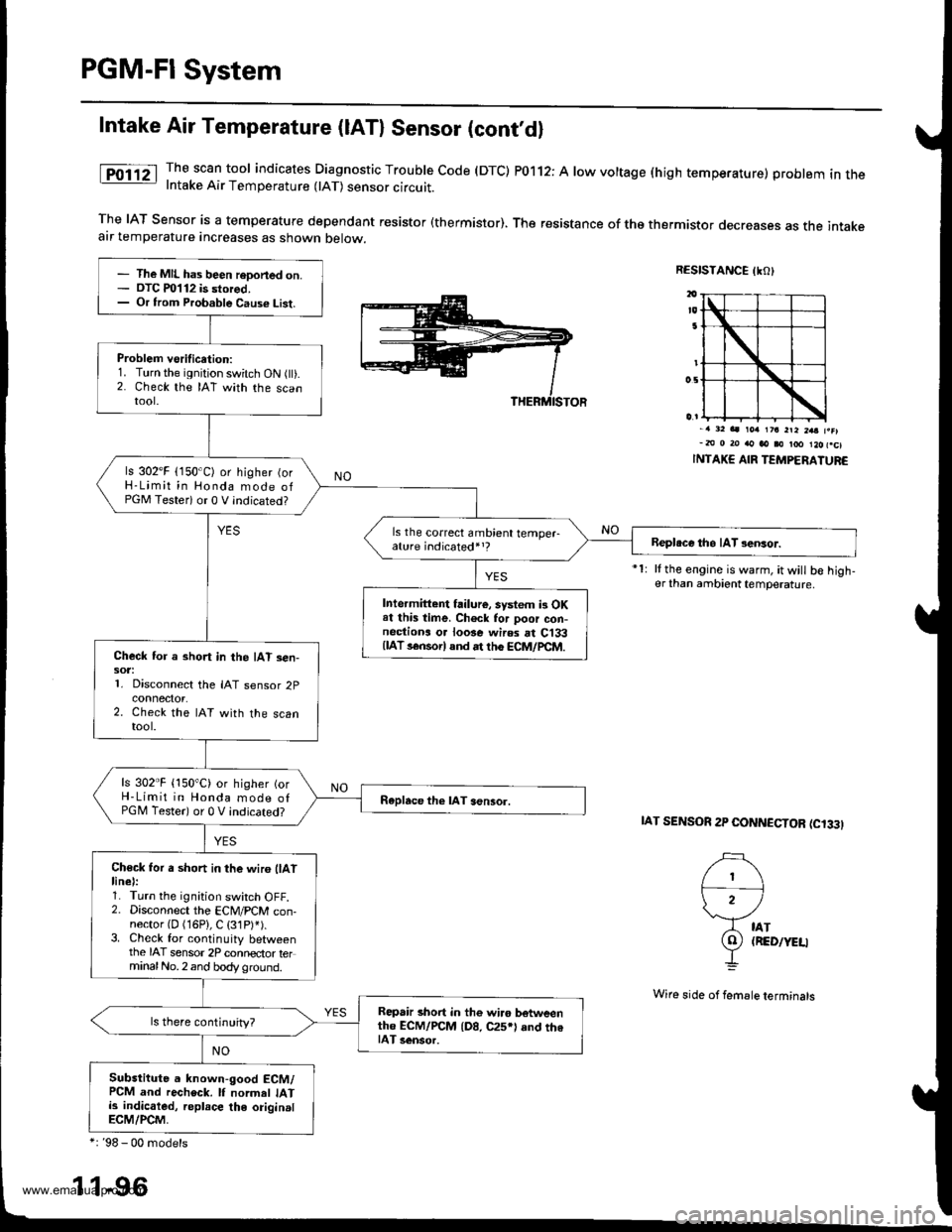
The scan tool indicates Diagnostic Trouble code (DTC) P0112: A low voltage (high temperature) problem in theIntake Air Temperature 0AT) sensor circuit.
The IAT Sensor is a temperature dependant resistor (thermistor). The resistance of tho thermistor decreases as the intakeair temperature increases as shown below.
RESISTANCE IKO)
i')
)2 /
A tAr
9) (RED/YEU
-L
-. 32 aa rorr 1?a 2ra 2aa f.el-m 0 20 rto ao i0 too l2ofcl
INTAKE AIR TEMPERATUR€
It the engine is warm, it will b€ high-er than ambient temperature.
IAT SENSOR 2P CONNCCTOR (C'33I
- The MIL has been reDoned on.- OTC m112 is stored,- Or from Probable Caus€ List.
Problem vsrification:1. Turn the ignition switch ON flt).2. Check the IAT with the scantool.
ls 302'F (150'C) or higher (orH-Limit in Honda mode ofPGM Testeri or 0 V indicated?
ls the correct ambient temper-ature indicated,,?Beploce tho IAT sensor.
Intermittent failure, system i3 OKat this time. Ch6ck for poor con-nectiona o. loose wires rt C133{lAT s€nsorl and rt th6 ECM/pCtr4.Check for a short in the IAT sen-sot:1. Disconnect the IAT sensor 2p
2. Check the IAT with the scantool.
ls 302"F {150"C) or higher {orH-Limit in Honda mode ofPGM Tester) or 0 V indicated?Raplace the lAT aensor.
Ch€ck for a short in the wir6 llAtlinel:1. Turn the ignition switch OFF.2. Disconnect the ECM/PCM con-nector {D (16P}, C (31P)').3. Check for continuity betweenthe IAT sensor 2P connector terminalNo.2 and body ground.
Repair short in the wi.o botweenth6 ECM/rcM {D8, C25*l and th6IAT 3ensor.
Substitute a known-good ECM/PCM and recheck. lf normel IATis indicaled, replace the originalECM/PCM,
*: '98 - 00 models
1 1-96
Wi16 side of femsle terminals
www.emanualpro.com
Page 299 of 1395
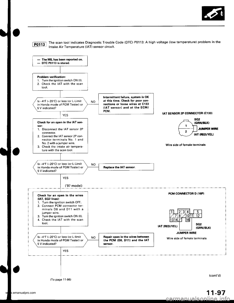
The scan tool indicates Diagnostic Trouble Code (DTC) P0113: A high voltage (low temperature) problem in the
Intake Air Temperature (lAT) sensor circuit.
IAT SENSOR 2P CONNECTOR ICl33I
sG2{GRN/BIIO
JUMPEN WNE
IAT IRED/YELI
Wire side ol female terminals
YES
_!!7rqd9ll_____-
FCM CONNECTOR O IT6PI
IAT IRED/YEL)sG2IGRN/BLK}
JUMPER w|BE
Wire side of female terminals
l
(cont'd)
11-97
The MIL has been reported on.OTC P0113 is stored.
Problem v€rification:1. Turn the ignition switch ON (ll).
2. Check the IAT with the scantool,
Intermiftent failure, syatem is OKat this time. Ch.ck for Door con-nections or loose wires at c133
llAT s6nsorl and at the ECM/PCM.
ls -4'F (-20"C) or less (or L Limitin Honda mode of PGM Tester)or5 V indicated?
Check lor an open in the IAT sen-sor:1. Disconnect the IAT sensor 2Pconnector,2. Connect the IAT sensor 2P connector terminals No. 1 andNo. 2 with a ,umper wire.3. Check the intake air tempera'ture with the scan tool.
ls -4'F (-20"C) or less (or L-Limitin Honda mode oI PGM Tester)or5 V indicated?Replace the IAT sensor.
Check lor en opan in the wires
llAT, SG2 lines):1. Turn the ignition switch OFF.2. Connect PCM connector ter-minals D8 and D11 with a
3. Turn the ignition switch ON lll).4. Check the IAT with the scantool.
Rgpair open in the wires b€tweenthe PcM (D8. D11) and rhe IAT3en30r,
ls -4"F {-20"C) or Iess (or Llimitin Honda mode ot PGM Tester)or5 V indicated?
(To page 11-98)
www.emanualpro.com
Page 300 of 1395
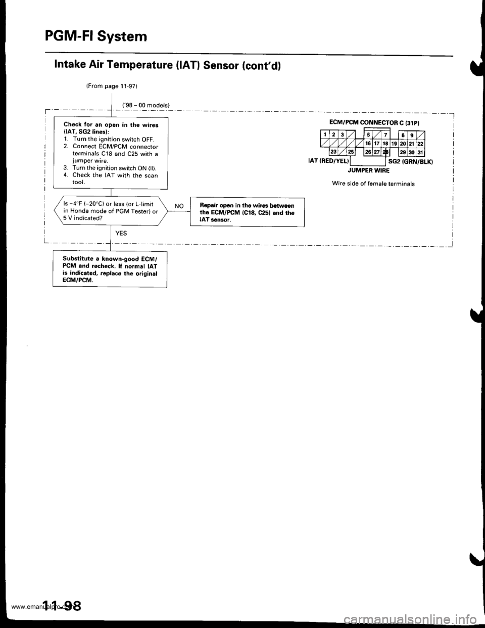
PGM-FI System
Check for an open in the wires{lAT, SG2lines):1. Turn the ignition switch OFF.2. Connect ECM/PCM connectorterminals C18 and C25 with ajumper wire.3. Turn the ignition switch ON (ll).4. Check the IAT with the scantool.
ls -4'F 1-20"C) or less (or L limitin Honda mode of PGM Testeri or5 V indicated?
Repsir op€n in the wirca batweenthe ECM/PCM 1C18, C25l and theIAT s€nsor.
Substitute a known-good ECM/PCM rnd recheck, lf normal IATis indicated, leplaco the originslECM/PCM.
Intake Air Temperature (lATl Sensor (cont'd)
(From page 11,97)
'l
ECM/PCM CINNECTOR C t3lPl
257II
./ 16171819 202122234 Wp,29c)31
sG2IAT {RED/YELI{GRN/BLK)
JUMPER WIRE
Wire side of fernale terminals
I
1 1-98
www.emanualpro.com
Page 301 of 1395
Engine Goolant Temperature (ECTI Sensor
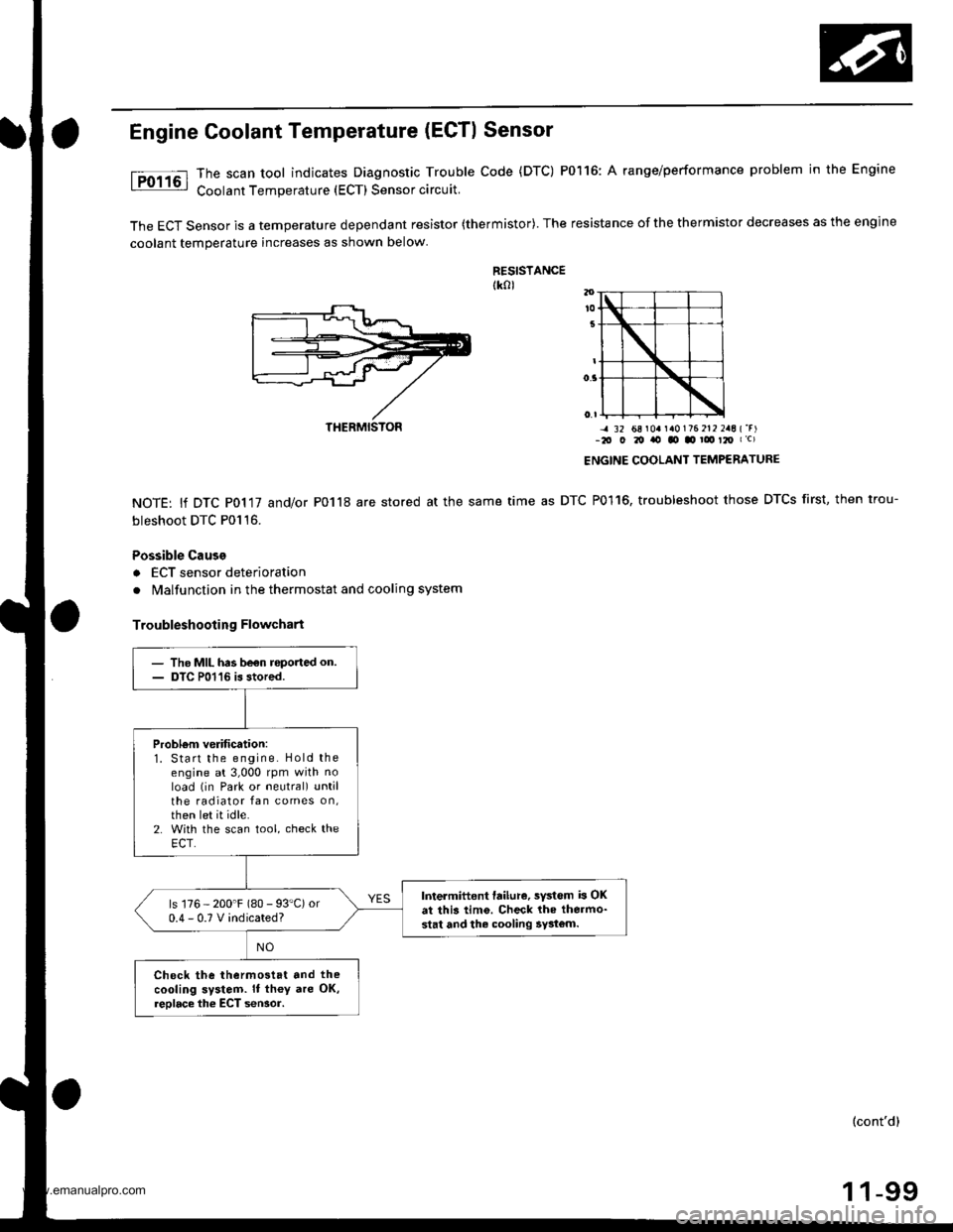
The scan tool indicates Diagnostic Trouble Code (DTC) P0116: A range/performance problem in the Engine
Coolant Temperature (ECT) Sensor circuit.
The ECT Sensor is a temperature dependant resistor (thermistor). The resistance of the thermistor decreases as the engine
coolant temperature increases as shown below
RESISTANCEtk0l
NOTE: lf DTC P0117 and/or P0118 are stored at the same
bleshoot DTC P0116.
Possible Cause
a ECT sensor deterioration
. Malfunction in the thermostat and cooling system
Troubleshooting Flowchart
-4 32 68 r0a r a0176 212 2aE {'r)-2O O 20 ito tO .o ! t2O I c)
ENGINE COOLANT TEMPERATURE
time as DTC P0116, troubleshoot those DTCS first, then trou-
THERMISTON
- The MIL has be€n roported on.- DTC P01'16 is stored.
Probl6m verification:1. Start the engine. Hold theengine at 3,000 rpm with noload (in Park or neutral) untilthe radiator fan comes on,then let it idle.2. With the scan tool, check theECT.
Intermittent failure, sYstem b OKat this tim6. Check lhe thermo-stat and the cooling 5y3tom.
ls 176 - 200'F (80 - 93"C) or0.4-0.TVindicated?
Check the thermostat and the
cooling system. It th€y are OK,reolace the ECT seNor.
(cont'd)
1 1-99
www.emanualpro.com