Page 613 of 1395
From page 14-96
Check Ior continuity betlveen the
B2O terminal and body ground,
and between the 822 terminal
and body ground.
Bepair open in the wirea
between the 820 and 822 te.mi-
nals and ground (G1011.
Check Lock-up Control Solenoid
Valve I fo. a Short Circuit:1. Disconnect the 2P connectorfrom the lock_u p control
solenoid valve A,/B assembly2. Check for continuity betweenthe D3 and 820 or 822 termi
nats.
Rep.ir short to ground in the wiie
between the D3 terminal and the
lock-uD control solenoid valve B.ls there continuity?
Measure Lock-up Control Solenoid
valve B Resistance at the solenoid
ConnedoMeasure the resistance between
the No. 1 terminal of the lock_up
control solenoid valve A/B
assembly connector and bodYground.
Replace the lock_up conirol
solenoid valve A/8 a$embly.ls the resistance 12 - 25 O?
Check for open in the wiro
betwoen the D3 terminal and the
lock-up control solenoid valve B.
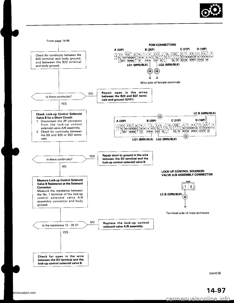
PCM CONNECTORS
B (25Pt c (31P1 D (16P1
rc1 rBRN/BLKk'
c$G2
{BRN/BLKI
t
Wire side ol female terminals
L(rcK.UP CONTROL SO1TNOID
VALVE A/B ASSEMBLY CONNECTOR
LC B IGRN/BLK)
(cont'd)
14-97
A {32P1
www.emanualpro.com
Page 614 of 1395
Electrical Troubleshooting ('98 - 00 Modelsl
Troubleshooting Flowchart - Lock-up Control Solenoid Valve B (cont,d)
From page 14 96
PCM CONNECTORSVB SOL (BLK/YEL}
LG1 (BBN/8LKI LG2 (BRN/BLKI
Wire side of Iomale terminals
Measuro VB SOL Voltago:1. Turn the ignition switch ON llt).2. Measure the voltage betlveenthe D5 and 820 or 822 terminals,
Check tor blown No. t5 (7.5 Alfuse in the underdash fu36/.elaybox. lf th6 fuse is OK, ..pair openin the wire betwooo tho D5 t.rmi-nel and thg underdash two/relayItox.
ls there battery voltage?
Check for loose terminal lit in thePCM connectors. ll n€ces3a.y,substitute a known-good pCM
and .€check.
A l32P)
14-98
www.emanualpro.com
Page 615 of 1395
TroubleshootingFfowchart - AIT Gear Position Switch {Short)
Possible Cau3e
. short in A/T gear position switch wire. Faulty A/T gear pGition switch
NOTE: Code 1705 (5) is set when the PCM receives two gear position inputs at
the same time,
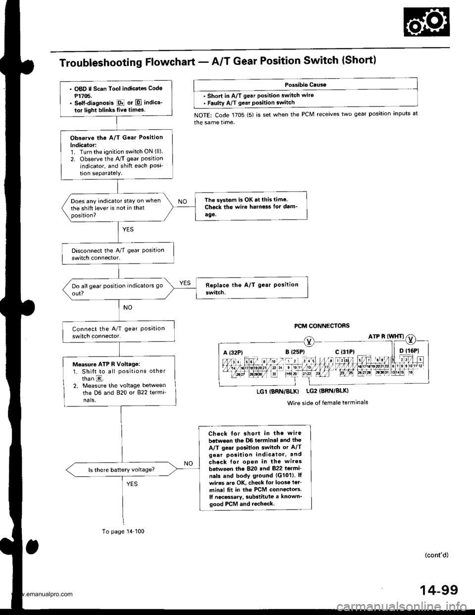
PCM CONNECTORS
A (32P1
LGl IBRN/BLK) LG2 (BRN/BLK)
Wire side of female terminals
' O8O ll Scan Tool indicatas Code
P1705.. self-diagnGi3 E or El indica'
tor light blinks five time3
Obs€rve the A/T Goar Position
lndicalor:1. Turn the ignition switch ON (ll).
2. Observe the A/T gear Positionindicator, and shift each Posi'tion seParatelY.
The system is OK at lhis time.
Check the wir€ harne3s fot dam'
age.
Does any indicator stay on when
the shift lever is not in thatposition?
Moasu.e ATP R Voltage:1. Shift to all positions other
than E.2. Measure the voltage between
the D6 and 820 or 822 termi-nals,
Check for short in the wire
betwoon thc DS terminal and tho
A/T gear position switch or A/Tgear porition indicatol, and
check for open in the wires
batween the 820 and 822 t6lmi'
nals and body ground 1G1011. lf
wires are OK, check lor loos€ i€r_
minel fit in the PCM connectors.
lf necBsarv, substittlle a known'good PCM and recheck.
To page'14-100
(cont'd)
14-99
www.emanualpro.com
Page 616 of 1395
Electrical Troubleshooting ('98 - 00 Modelsl
Troubleshooting Flowchart - A/T Gear position switch (short) (cont'dl
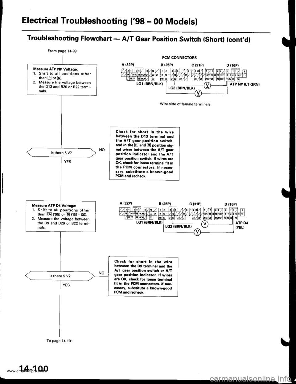
FCM CONNECTORS
B t25Plc (31P)
Wire side of lemale terminals
A t32Pl
LGl {BRN/BLK)
From page 1 4-99
To page 14-101
Measur. ATP NP Voltago:1. Shift to all positions otherthan E or E.2. Measure the voltage belweenthe 013 and 820 or 822 termi-nats.
Check for short in the wir6b.twoen tha Dl3 terminal andthe A/T go.r polition 3witch,and in th6 El and E poiition sig-nal wir.! betwoen the A/T garrpo3ition indicetor and the A/Tgarr position switch. lf wi.6s areOK, check for loole torminal fit intho PCM connccto.s, lf necca-sary, lubstituto a known-goodPCM and rocheck.
Mcrsure ATP D4 Vohrg6:1. Shift to all positions otherthan E {'98) or El ('99 - oo).2. Measure the voltage betweenthe Dg and 820 or 822 termi-nals.
Check tor Bhort in the wi..bctw6cn thg Dg torminal and theA/T ge.r position .witch or A/Tgeor poaition indicator. lf wiaaaare OK, ch.ck lor loose torminalfit in the PICM conn.cto6. lf n€c-e3sary, subgthute r lnown-goodrcM and roch6d(.
ATP NP ILT GRNI
a t32Pl
LGl IERN/BLK}
14-100
www.emanualpro.com
Page 617 of 1395
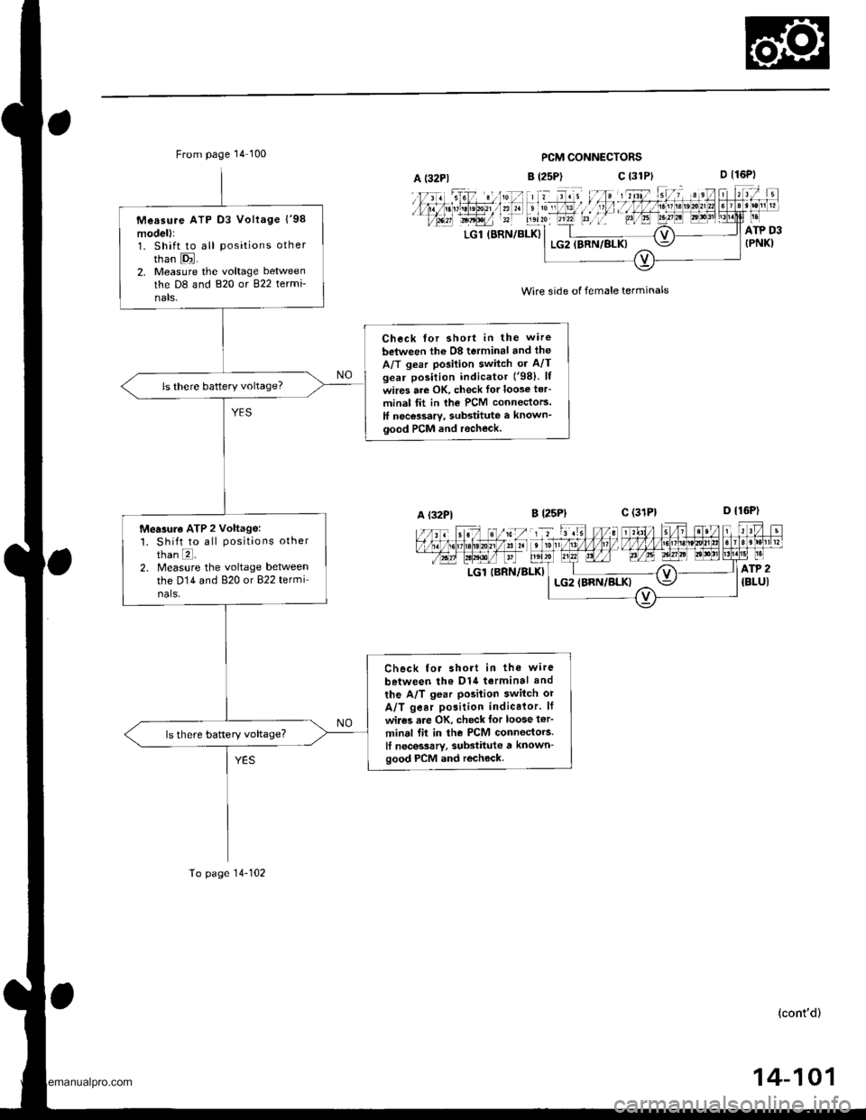
From page 14 100PCM CONNECTORS
B (2sP)c (31P}
' t d. , lll;;l';nl, :if
D t16P)
D {16P1
ATP D3{PNK)LGl (BRN/BLK}LG2IBRN/BLK)
Wire side of female terminals
B l25Plc (31P1
LGl IBRN/BLKI
A (32P1
Measure ATP D3 Vollage l'98model):1. Shift to all positions other
than E.2, Measure the voltage between
the D8 and 820 or 822 termi-
nals-
Check for shott in the wire
belween lh6 08 terminal and the
A/T gear posilion switch or A/Tgear position indicator ('98) lf
wires are OK, check lor loose ter-
minal tit in rhe PCM connectors.
ff necessary, substitute a known_good PCM and recheck.
ls there battery voltage?
Mearure ATP 2 voltage:1. Shift to all positions otherthan E.2. Measure the voltage betweenthe D14 and 820 or 822 termi
nals.
Check for short in the wire
between tho D1{ terminal and
the A/T gear posilion switch or
A/T gear position indicalor. lf
wiles are OK, check for loose t€r'
minal fit in the PCM connectors.It necessarv, substitute a known-good PCM and recheck.
To page 14-102
(cont'd)
14-101
www.emanualpro.com
Page 618 of 1395
Electrical Troubleshooting ('gg - 00 Modelsl
Troubleshooting Flowchart - A/T Gear position switch {short) (cont,d)
PCM CONNECTORS
B t25Ptc t3lPlD {16P1
LGl {BRN/BLK)
Wire side of female terminals
From page 14 101
Measure ATP 1 Voltag€:1. Shift to all positions otherthan E.2. Measure the voltage betweenthe D15 and 820 ot 822 tetmi-nals.
Chock lor short in the wirebetween the D15 terminal andthe A/T gear position switch orA/T gear position indicator. lfwires a.e OK, ch6ck for loos€ t6r-minal fil in tho PCM connectorc.ll neco$ary, substiiute a known-good PCM and rechsck.
Chock for loose terminalfit in thePCM connectors. lf nocessary,sub3titut€ s known-good PCMand recheck.The system 3hould be OK at thispoint. lf any indicators stay onwhen the shift lever is not in iheselect€d position, pertorm thistroubleshooting tlowchart again.
www.emanualpro.com
Page 619 of 1395
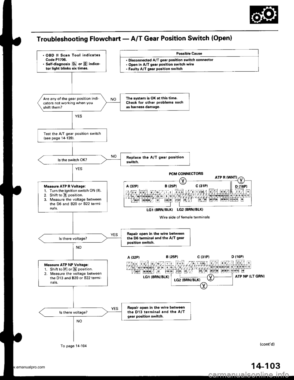
Troubleshooting Flowchart - A/T Gear Position Switch (Open)
Po$iblg Cause
. Dbconnected A/T gear position switch connoctor. Open in A/T gear po3ition switch wiro. Faulty A/T g€ar position switch
Wire side of female terminals
LGl {SRN/BLK)
{cont'd)
P,CM CONNECTORS
LGT(BNN/BLKI LG2IBRN/BLK)
A {32P)c l31P)
ATP NP (LT GRN}
. OBD ll Scan Tool indicatesCodo Pl706.. Self-diagnosis Fl or E indica-to. lighl blinks six times.
The system is OK.tthis time.Check for oth6r probl€ms suchas harne3s damage.
Are any ofthe gear position indicators not working when you
shift them?
Test the A/T gear position switch(see page 14-139).
Measure ATP R Vohago:1. Turn the ignition switch ON (ll).
2. Shitt to E position.
3. Measure ihe voltage betweenthe D6 and 820 ot 822 tetfiinals,
Repair open in tho wiro betwoenthe D6 terminal and the A/T gear
oosition switch.
Measure ATP NP Volt.g€:1. Shift to Elor E position.
2. Measure the voltage betweenthe D13 and 820 or 822 terminals,
Repair open in the wiro betweenth€ Dl3 terminal and th€ A/Tgesr posilion awitch.
To page 14-104
14-103
www.emanualpro.com
Page 620 of 1395
Electrical Troubleshooting ('98 - 00 Model)
Troubleshooting Flowchart - A/T Gear Position Switch (Open) (cont'd)
PCM CONNECTORS
B {25Ptc (31P|
LGl IERN/BLKI
Wire side of female terminals
LGl {BRN/BLKI
LGl {BRN/ELXI
From page 14-103
Me.sure ATP D4 Vohrge:1. Shift to E 1'98) or E ('99 -
00) position.2. Measure the voltage betweenthe Dg and 820 or 822 termi-nats.
Repair opon in th6 wire betweentho m tarminal and the A/T gealposition swhch.
Me..ure ATP 03 Vohage l'98modell:1. Shift to E position.2. Measure the voltage betweenthe DB and 820 or 822 tetmi-nals,
Repair open in the wire botwoonth6 08 terminal .nd the A/T geatposition switch (381.
Measuro ATP 2 Voltage:1. Shilt to E position.2. Measure the voltage betweenthe D14 and 820 or 822 terminats.
Repair opon in the wire betweenthe D14 t€.minal end the A,/Tgear po3ition switch,
To page 14 105
www.emanualpro.com